Step 7: finish hanging fan a – Hunter Fan 41675-01 User Manual
Page 4
41675-01 01/07/2004 3 © 2004 Hunter Fan Company™
41675-01 01/07/2004 4 © 2004 Hunter Fan Company™
IMPORTANT! Before installing this control make sure the posi-
tion of the jumper switches of the transmitter and receiver are
matched. If they are not matched, the control will not function.
When two or more fans are located near each other, you may
desire to have each of them set to a different code, so that the
operation of one fan will not affect another. This is accomplished
by changing the position of any one or more of a group of 3
jumpers grouped together in the transmitter. The receiver located
has the same set of 3 jumpers which must also be changed to
match the transmitter settings.
These jumpers are very small and can best be operated by using
a small pair of pliers or tweezers.
In the transmitter, the jumpers are readily accessible from the
battery compartment.
IMPORTANT! When you change jumper switches, make sure
the battery is not connected to the transmitter.
Cut the lead wires from the fan a maximum length of 3 1/2”
from the top of the pipe ball assembly or the top of the motor
adapter depending upon the installation method chosen. Using
wire strippers on the 22AWG setting, strip all lead wires coming
from the fan 5/16”. Note: If you are not comfortable stripping
wires, please seek help from a qualified electrician.
A.
Install a fresh 12-volt battery into the transmitter (included).
Place the receiver inside the canopy. First make sure the oval
shaped holes in the bottom of the receiver and dip switches
are facing down, toward the bottom of the canopy. Spread the
receiver lead wires to each side and feed the wires from the top
of the fan through the open slot in the receiver. Now place the
receiver into the canopy making sure the slot in the receiver
is aligned with the hook in the ceiling plate. When properly
installed the hook in the ceiling plate will fit inside the open
slot of the receiver. If the hook and slot do not line up with each
other, rotate the receiver until the two parts align. The canopy
can not be attached to the ceiling plate unless the hook is posi-
tioned in the receiver slot.
B.
Connect electrical supply leads from the motor, using
approved connectors (smaller wire nuts). Match the colors and
connect all the shorter wires from the receiver to the matching
color wire from the fan.
Connect the longer white from the receiver to the white power
(common) wire using one of the larger wire nuts. Connect the
longer black wire from the receiver to the black power wire
using one of the larger wire nuts.
Run the thin white antenna wire from the receiver through one
of the slots in the ceiling plate and outside the canopy (when
installed)..
Connect the ground wire to the green lead wires from the ceiling
plate and the hanger ball using one of the larger wire nuts.
After wiring is completed, check all connections to ensure that
they are tight and there are no bare wires visible at the wire
connectors.
CAUTION: No bare wire or wire strands should be visible after
making connections.
C.
After making the wire connections, the wires should be
spread apart with the white and green wires on one side of the
outlet box and the other wires on the other side of the outlet box.
The splices should be turned upward and pushed carefully into
the outlet box.
Step 7: Finish Hanging Fan
A.
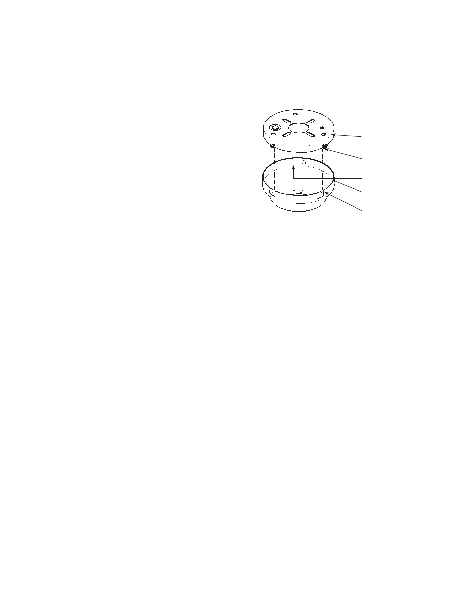
The ceiling plate has (6) mounting screw holes located
on the side. Use (3) of the holes that are equal distance apart.
Install (2) #10-32 x 1/2” Phillips round head screws halfway into
two of these holes. See Figure 7.
Remove the fan from the ceiling plate hook. Make sure not to
break any wire connections. The canopy has (2) mating slots
and (1) mating hole. See Figure 7.
B.
Position (2) slots in canopy directly under and in line with
(2) mounting screws in ceiling plate. Lift fan until ceiling plate
mounting screws are seated in bottom of slots in canopy. Rotate
fan clockwise until both mounting screws drop into slot recesses.
Tighten screws securely. Install third screw in mounting hole.
CAUTION: Failure to properly tighten the (3) screws could
result in the fan falling.
NOTE: For the ball hanging fan configuration make sure the (2)
grooves in the ball are engaged with the (2) tabs in the canopy.
Failure to do so could result in the fan falling. See Figure 5C.
FIGURE 7
CEILING PLATE
MOUNTING SCERW
MOUNTING HOLE
CANOPY
MOUNTING RECESS