Heat & Glo Fireplace 6000TV-OAK User Manual
Page 14
Heat & Glo • 6000TV-OAK, 6000TV-OAK-IPI • 384-900 Rev. N • 11/05
14
!
C. Bedroom Installation in Canada
This model MUST NOT be vented into a vent system in-
stalled exterior to a building. The part of the vent system
above the roof line can be exterior to the building.
D. Vent Termination
WARNING: MAJOR U.S. BUILDING CODES
SPECIFY MINIMUM CHIMNEY AND/OR VENT
HEIGHT ABOVE THE ROOF TOP. THESE MIN-
IMUM HEIGHTS ARE NECESSARY IN THE IN-
TEREST OF SAFETY. FIGURE 6 AND TABLE
SHOW MINIMUM HEIGHTS, PROVIDED THE
TERMINATION CAP IS AT LEAST 8-FEET
FROM A VERTICAL WALL.
!
ROOF PITCH
H (MIN.) FT.
FLAT TO 6/12
1.0
OVER 6/12 TO 7/12
1.25
OVER 7/12 TO 8/12
1.5
OVER 8/12 TO 9/12
2.0
OVER 9/12 TO 10/12
2.5
OVER 10/12 TO 11/12
3.25
OVER 11/12 TO 12/12
4.0
OVER 12/12 TO 14/12
5.0
OVER 14/12 TO 16/12
6.0
OVER 16/12 TO 18/12
7.0
OVER 18/12 TO 20/12
7.5
OVER 20/12 TO 21/12
8.0
Figure 6. Vent Termination
TERMINATION
CAP
12
X
ROOF PITCH
IS X/ 12
LOWEST
DISCHARGE
OPENING
H (MIN.) - MINIMUM HEIGHT FROM ROOF
TO LOWEST DISCHARGE OPENING
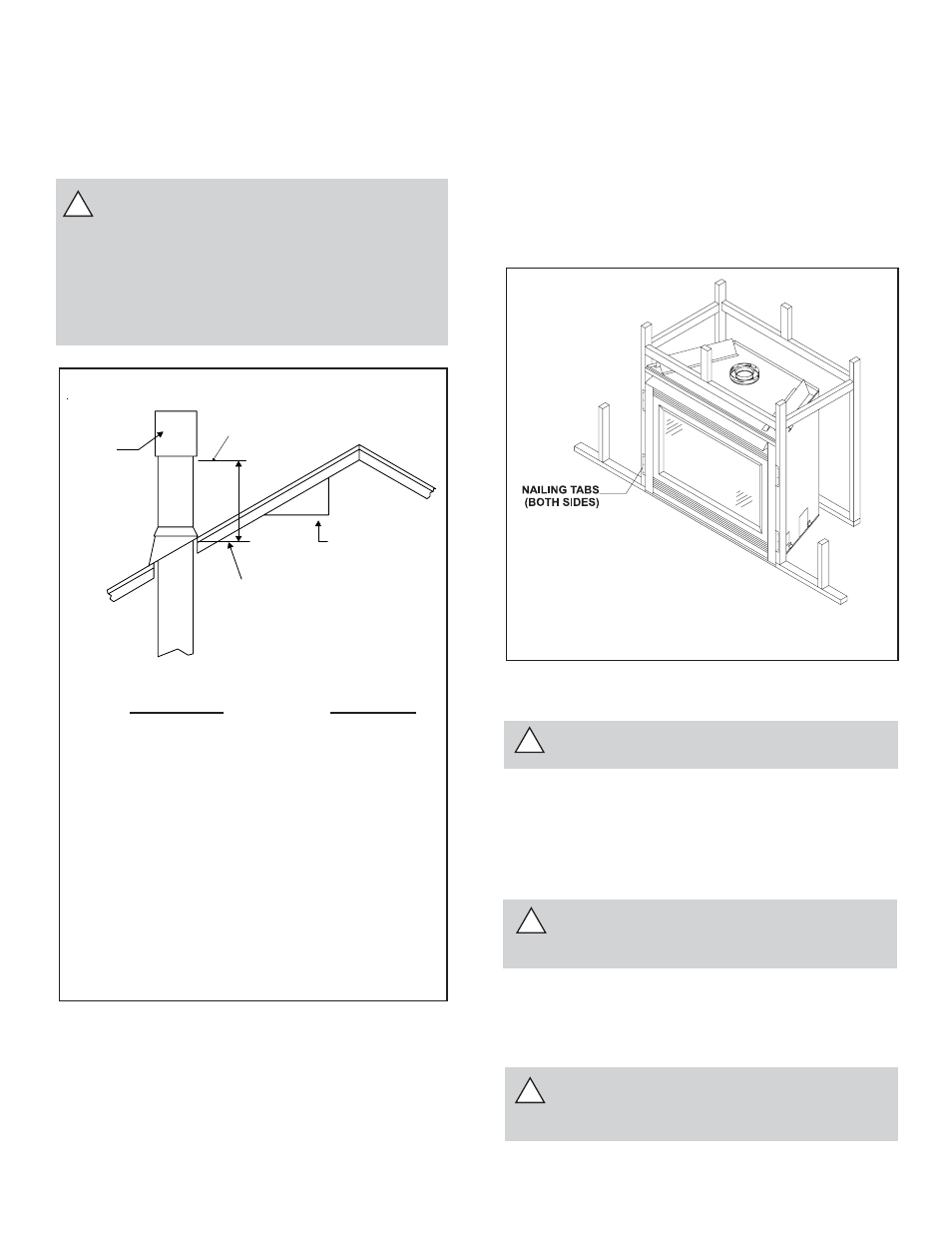
Step 5. Positioning, Leveling, and
Securing the Fireplace
To properly position, level, and secure the fireplace:
• Place the fireplace into position (see Figure 7).
• Level the fireplace from side to side and from front to
back.
• Shim the fireplace with non-combustible material, such
as sheet metal, as necessary.
• Secure the fireplace to the framing by nailing or screwing.
!
!
Figure 7. Proper Positioning, Leveling,
and Securing of a Fireplace
Step 6. The Gas Control Systems
WARNING: THIS UNIT IS NOT FOR USE WITH
SOLID FUEL.
Two types of gas control systems are used with these models:
Standing Pilot Ignition and Intermittent Pilot Ignition (IPI).
Standing Pilot Ignition System
This system includes millivolt control valve, standing pilot,
thermopile/thermocouple flame sensor, and piezo ignitor.
WARNING: 110-120 VAC MUST NEVER BE
CONNECTED TO A CONTROL VALVE IN A
MILLIVOLT SYSTEM.
Intermittent Pilot Ignition (IPI) System
The IPI system includes a 3V control valve, electronic mod-
ule, and intermittent pilot.
WARNING: CONTINUOUS 110-120 VAC SER-
VICE MUST BE WIRED TO THE FIREPLACE
JUNCTION BOX.