Specifications of control and logic connections – Hitachi SJ100 User Manual
Page 123
Example Wiring Diagram
Oper
ations
and Monitor
ing
4–6
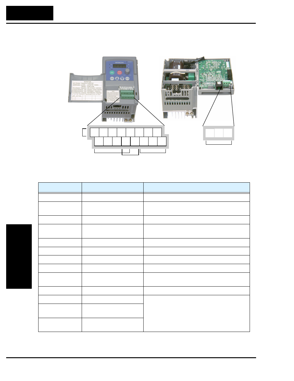
Specifications of Control and Logic Connections
The control logic connectors are located just behind the front panel half-door. The relay
contacts are accessible behind the main door. Connector labeling is shown below.
Specifications for the logic connection terminals are in the following table:
Note 1:
The two terminals [L] are electrically connected together inside the inverter.
Relay
contacts
Logic
inputs
Analog
inputs
Analog
output
Logic
outputs
12 11
1
2
3
4
5
6
L
L
H O OI
FM CM2
P24
AL0
AL2
AL1
Terminal Name
Description
Ratings
[P24]
+24V for logic inputs
24VDC, 30 mA max (do not short to terminal L)
[1], [2], [3], [4], [5],
[6]
Discrete logic inputs
27VDC max. (use P24 or an external supply refer-
enced to terminal L)
[L] (top row) *1
GND for logic inputs
sum of input 1-6 currents (return)
[11], [12]
Discrete logic outputs
50mA maximum ON state current,
27 VDC maximum OFF state voltage
[CM2]
GND for logic outputs
100 mA: sum of 11 and 12 currents (return)
[FM]
PWM (analog/digital) output 0 to 10VDC, 1 mA, PWM and 50% duty digital
[L] (bottom row) *1 GND for analog inputs
sum of OI, O, and H currents (return)
[OI]
Analog input, current
4 to 19.6 mA range, 20 mA nominal
[O]
Analog input, voltage
0 to 9.6 VDC range, 10VDC nominal,
input impedance 10 k
Ω
[H]
+10V analog reference
10VDC nominal, 10 mA max
[AL0]
Relay common contact
250 VAC, 2.5A (R load) max.,
250 VAC, 0.2A (I load, P.F.=0.4) max.
100 VAC, 10mA min.
30 VDC, 3.0A (R load) max.
30 VDC, 0.7A (I load, P.F.=0.4) max.
5 VDC, 100mA min.
[AL1]
Relay contact, normally
closed during RUN
[AL2]
Relay contact, normally open
during RUN