Mounting the thermostat, Do not overtighten screws, Or damage to subbase can result – Honeywell Q674F User Manual
Page 9
69-0268—11
9
T874G,R MULTISTAGE HEAT PUMP THERMOSTATS AND Q674F,J,L SUBBASES
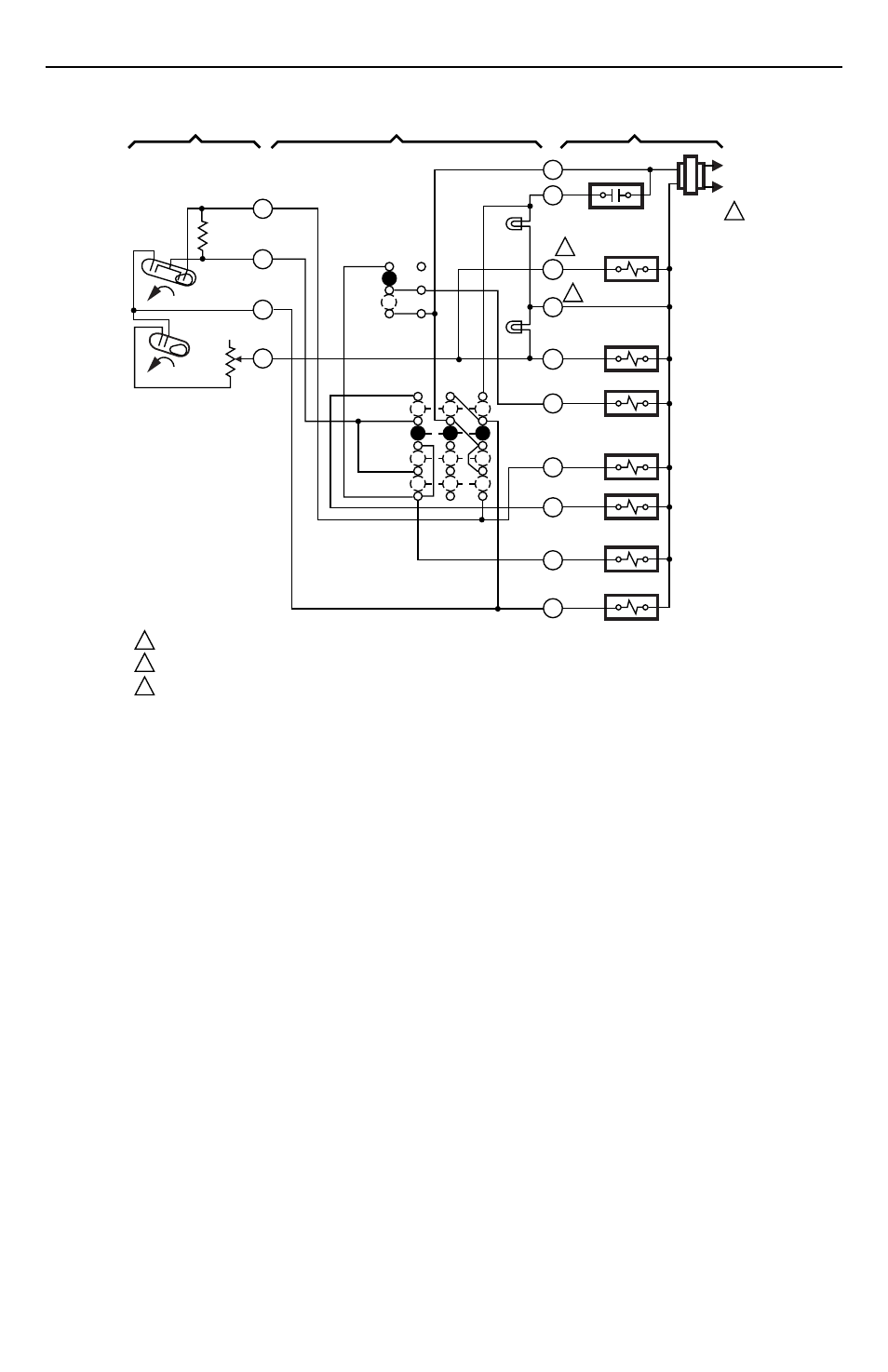
Fig. 10. Internal schematic and typical wiring diagram for T874R/Q674L in heat pump system. Includes EM. HT.
and AUX. HT. LEDs.
L1
(HOT)
L2
1
X
L
W2
EM. HT.
LED (RED)
AUX. HT.
LED (GRN)
AUX. HT.
RELAY
FAN RELAY
"B" RELAY
G
COOL CHANGEOVER
VALVE
EM. HT. RELAY
COMPRESSOR
CONTACTOR
O
Y
E
B
SYSTEM
SWITCH
EM. HT.
HEAT
OFF
COOL
H1/C1
ANTICIPATOR
C1
H1
FALL
H2
W3
AUX. HT.
RELAY
H2
ANTICIPATOR
1
2
3
2
3
POWER SUPPLY. PROVIDE DISCONNECT MEANS AND OVERLOAD PROTECTION AS REQUIRED.
TERMINAL LABELED C/X ON SOME MODELS.
W3 TERMINAL AVAILABLE ON SOME MODELS ONLY.
M3683A
AUTO
ON
FAN
SWITCH
FALL
R
2
3
4
6
THERMOSTAT
SUBBASE
SYSTEM COMPONENTS
Mounting the Thermostat
³
Remove the thermostat cover by pulling the bottom
edge of the cover outward and away from the base
until it snaps free of the retaining posts.
NOTE:
The cover is hinged at the top and must be
removed by pulling the bottom edge
outward and away from the base.
·
Carefully remove and discard the polystyrene
packing insert that protects the mercury switches
during shipment.
»
Turn over the thermostat base and note the spring
fingers that engage the subbase contacts. Make
sure the spring fingers are
not
bent flat, preventing
proper electrical contact with the subbase.
¿
Note the tabs along the top inside edge of the
thermostat base. The tabs fit into the corresponding
slots on the top of the subbase. Mount the
thermostat on the subbase.
´
Align the two captive mounting screws in the
thermostat base with the posts on the subbase. See
Fig. 14. Tighten both screws.
Do not overtighten
screws
or damage to subbase can result.