Type of heating and cooling equipment – Honeywell EXCEL 10 W7752D User Manual
Page 15
EXCEL 10 FCU CONTROLLER LNS PLUG-INS USER GUIDE
EN2B-0285GE51
R0909
13
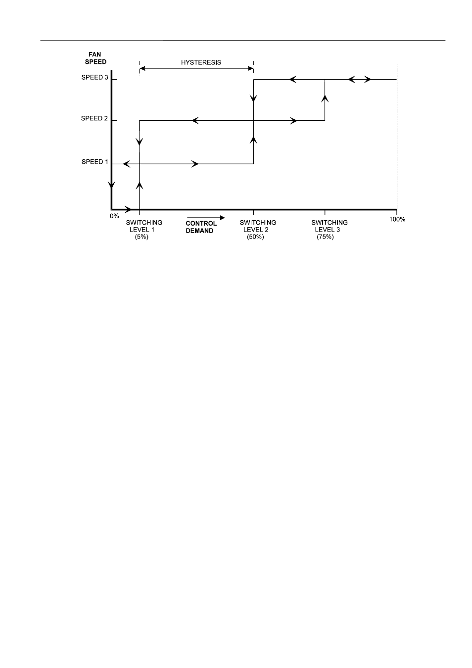
Fig. 9. Three-speed fan switching and hysteresis, cooling mode (defaults for switching levels shown)
Type of Heating and Cooling Equipment
Excel 10 FCU Controllers can operate with either two-pipe or
four-pipe systems. A two-pipe system requires a changeover
input to the controller (hardware or network input).
Excel 10 FCU Controllers can operate with a variety of
actuators for heating and cooling equipment. Floating
actuators can be used; this requires that the valve run time be
specified during configuration of the controller.
The actuator runtimes can be configured in the range 20 sec
to 600 sec in steps of 1 second.
Valves will be synchronized by driving the valve fully closed
(150% of the valve run time) under the following conditions:
• whenever the control level reaches 0% or less;
• at
power-on;
• whenever the occupancy status changes to a lower mode,
e.g., from occupied to standby or unoccupied;
• when synchronization has not taken place within the last
24 hours.
Once synchronization has been completed, the output control
will be returned to the normal control loop.
Valve action can be configured as either direct or reverse.
When in a two-pipe system with a changeover input, a floating
actuator can be used which has the middle position (50%) as
the zero energy position. The cool range is then 0 to 50% and
the heat range 50 to 100%. The output must be configured as
floating-mid.
Multi-stage systems can be controlled with up to three
different stages of heating/cooling control. Switching levels
are specified in % of control level (see Fig. 10) as is a
hysteresis setting which applies to all switching levels.
Heating and cooling switching levels and hysteresis are
specified separately. Min. OFF times can be configured, and
for one-, two- and three-stage systems, a min. ON time can
also be configured.
PWM electronic valves and thermal actuators can also be
connected and can be configured as either direct or reverse
action. The cycle time must be specified during configuration.
In the case of PWM valves, the zero and full positions must
also be configured.
Additionally, the W7754K1001 features an extra socket
(located to the left of the terminal blocks) containing a digital
output suitable for connection to a solid-state relay employed
for low-voltage PWM control in high-current electric reheat
applications.