Honeywell COMMERCIALPRO TB7220U User Manual
Page 12
TB7220U COMMERCIALPRO™ PROGRAMMABLE THERMOSTAT
62-0221—05
12
NOTE: Press the Done key to exit the Installer System Test.
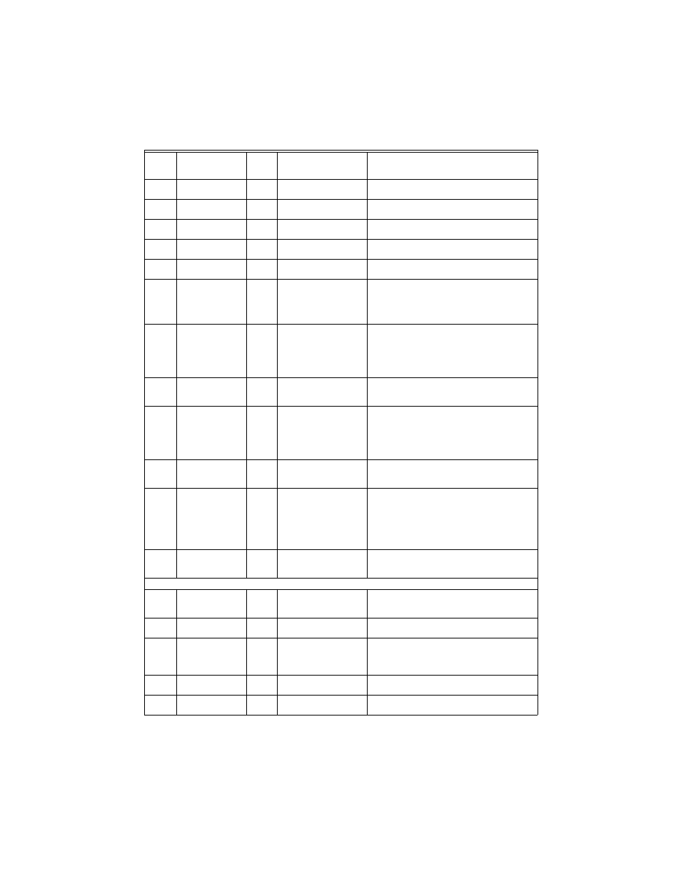
0600
Heat Temperature
Range Stops
90
40 to 90°F (4 to 32°C)
Only shown if system has heat stages (ISU 0170).
0610
Cool Temperature
Range Stops
50
50 to 99°F (10 to 37°C)
Only shown if system has cool stages (ISU 0170).
0640
Clock Format
12
12—12 Hour
24—24 Hour
0650
Extended Fan-on
time Heat
0
0—Off
90—90 seconds
Not displayed with cool-only systems (ISU 0170)
or with fan set to system control (ISU 0180 at 0).
0660
Extended Fan-on
time Cool
0
0—Off
40—40 seconds
Only shown for systems with cool stages (see ISU
0170).
0670
Keypad Lockout
0
0—Unlocked
1—Partial Lockout 1
2—Partial Lockout 2
3—Fully Locked
Unlocked: All functions accessible.
Partial 1: Locks all but Holiday, Override, and Up/
Down.
Partial 2: Locks all but Holiday and Override.
Full: Entire interface locked/non-functional.
0680
Temperature
Control Heat
2
1—Less Aggressive
2—Standard
3—More Aggressive
Only shown if system has heat stages (ISU 0170).
Only integral gains affected. Affects control
operation in all control regimes (not just recovery
or setpoint change).
More Aggressive stops signal prior to reaching the
setpoint. (For use with oversized equipment.)
0685
Recovery Heat
Ramp Rate
5
0-20°F/hour
Only shown if system has heat stages (ISU 0170).
0 disables ramped recovery (step setpoint change
at period start time).
0690
Temperature
Control Cool
2
1—Less Aggressive
2—Standard
3—More Aggressive
Only shown if system has cool stages (ISU 0170).
Only integral gains affected. Affects control
operation in all control regimes (not just recovery
or setpoint change).
More Aggressive stops signal prior to reaching the
setpoint. (For use with oversized equipment.)
0695
Recovery Cool
Ramp Rate
3
0-20°F/hour
Only shown if system has cool stages (ISU 0170).
0 disables ramped recovery (step setpoint change
at period start time).
0700
Temperature
Display Offset
0
-3 (-1.5)— -3°F (-1.5°C)
-2 (-1.0)— -2°F (-1.0°C)
-1 (-0.5)— -1°F (-0.5°C)
0 (0.0)—0°F (0.0°C)
1 (0.5)—1°F (0.5°C)
2 (1.0)— 2°F (1.0°C)
3 (1.5)—3°F (1.5°C)
This offset applies to both the control temperature
and to the display temperature for indoor sensor
(and remote indoor sensor).
0710
Restore Factory
Defaults
0
0—No
1—Yes
Resets all ISU parameters to default values and
resets the schedule to default (see Table 5).
Retains only calendar settings and time.
INSTALLER TESTS
Test 1
Installer Test
Cool
0
0—Off
1—Cool Stage 1
2—Cool Stage 2
Test 2
Installer Test
Fan
0
0—Off
1—Fan On
Test 3
Installer Test
Heat
0
0—Off
1—Heat Stage 1
2—Heat Stage 1 and 2
3—Heat Stage 1,2 and 3
Test 4
Installer Test
Auxiliary Heat
0
0—Auxiliary Heat Off
1—Auxiliary Heat On
Test 8
Installer Test
TOD/Economizer
0
0—TOD/Economizer Off
1—TOD/Economizer On
Table 4. Installer Setup Menu. (Continued)
Installer
Setup
Number
Installer Setup
Name
Default
Setting
All Settings
Notes