B) connection to a closed loop system, Fig. 5, Kml-700mwh-m connection to a closed loop system – Hoshizaki KML-700MWH-M User Manual
Page 12
12
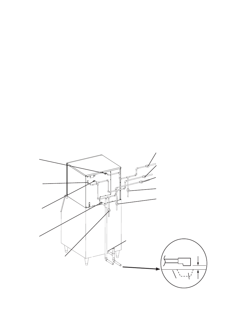
Condenser Return Line
Shut-Off Valve
Condenser Return Line
Drain Valve
Icemaker
Drain Outlet
3/4" FPT
Icemaker
Water Supply
Inlet
1/2" FPT
Fig. 5
Condenser
Water Supply
Inlet
1/2" FPT
Condenser
Return Outlet
3/8" FPT
Separate piping to approved drain.
Leave a 2-inch (5-cm) vertical air
gap between the end of each pipe
and the drain.
Icemaker
Bin Drain Outlet
3/4" FPT
2-inch (5-cm) air gap
Floor Drain
Bin
Icemaker Water Supply
Line Shut-Off Valve
Icemaker Water Supply Line
Drain Valve
Condenser Water Supply Line
Shut-Off Valve
Condenser Water Supply Line
Drain Valve
KML-700MWH-M
Connection to a Closed Loop System
b) Connection to a Closed Loop System
• Condenser water supply inlet is 1/2" female pipe thread (FPT). A minimum of 3/8" OD
copper tubing is recommended for the condenser water supply line.
• Condenser return outlet is 3/8" FPT. A minimum of 3/8" OD hard pipe is recommended for
the condenser return line.
• Shut-off valves and drain valves should be installed at both the condenser water supply
inlet and condenser return outlet.
• The water supply to the condenser should not drop below 4 GPM.
• The pressure differential between the condenser water supply inlet and condenser return
outlet must be no less than 10 PSIG.
• When using a glycol blend, the solution mixture should be less than 30% glycol.
• In order to maintain the proper high side pressure, the condenser water supply inlet
temperature should not drop below 45°F (7°C) and the condenser return outlet
temperature must be in the 104°F to 115°F (40°C to 46°C) range. Once the icemaker
installation is complete, confirm the condenser return outlet temperature 5 minutes
after a freeze cycle starts. If the outlet temperature is not in the proper range, adjust the
water-regulating valve to bring it into range.