Step 9: light kit installation a, Step 10: operation of fan a, Speed control – Hunter Fan 40955-01 User Manual
Page 4
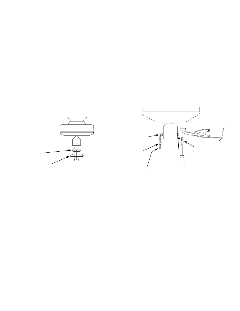
FIGURE 11
PULL CHAIN
SWITCH
BLADE MOUNTING
SCREWS
NOTE: MAKE
CERTAIN ALL
SCREWS ARE
TIGHT.
BREAKAWAY
CONNECTOR
REVERSING
SWITCH
PURCHASED ACCESSORY
CHAIN (IF DESIRED)
B.
Remove the screws and rubber bumpers from the motor
hub. Insert a mounting screw (provided) in hole in blade brack-
et. Use a screwdriver to hold in place. Align blade holes with
mounting holes in hub by turning screw and readjusting blade
bracket until screw mates with threaded hole in hub. Do not
tighten until both screws have been put in blade bracket. Repeat
for all blades. See Figure 10.
C.
A blade balancing kit has been provided with your fan.
Should the fan wobble in operation, you may use this kit to cor-
rect the balance per the instructions supplied with the kit.
Step 9: Light Kit Installation
A.
Install the light kit in accordance with the instructions sup-
plied with it.
NOTE: Some Hunter fans require a special adaptor plate
between the switch housing and the light kit. This plate is pro-
vided with those fans which need it. It should be installed as
shown in Figure 10. If the switch housing on your fan is 3
1
⁄
4
"
diameter or less you do not need the adaptor, mount the light kit
directly to the switch housing.
Step 10: Operation of Fan
A.
Turn electrical service on at main panel.
B.
Switch operates in this sequence: “High,” “Medium,”
“Low,” “OFF.” Pull chain slowly to operate. Also, release the
chain slowly so as to prevent chain from flying up into blades,
possibly resulting in damage to blades, or pull chain. The break-
away connector is designed to separate from the chain at a pre-
determined force. If this separation occurs, simply reinsert the
connector. It can be reused again and again. See Figure 11.
C.
Motor is electrically reversible. When first operating fan,
determine direction of air flow. If you wish to change direction,
switch fan off and allow to stop. Slide reversing switch to the
opposite position and switch fan back on. See Figure 11.
Speed Control
As an option, a wall mounted speed control switch is available
from your Hunter dealer.
FIGURE 10
LIGHT KIT
ADAPTOR
LIGHT KIT
40955-01 1/91
©1991 HUNTER FAN CO.™
-4-