Step 4: installation of ceiling plate a, Step 5: fan assembly low profile fan a, Hanging fan – Hunter Fan 40955-01 User Manual
Page 2
40955-01 1/91
©1991 HUNTER FAN CO.™
-2-
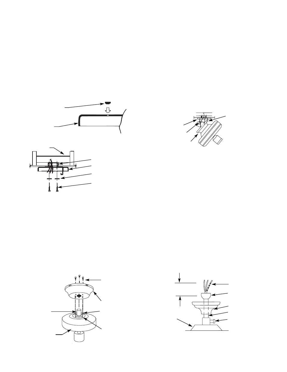
Step 4: Installation of Ceiling Plate
A.
Install the (3) rubber bushings into the top of the ceiling
plate by inserting small side of the bushing into the three holes
in the ceiling plate. See Figure 4A.
B.
Thread the lead wires through the opening in the ceiling
plate and install the ceiling plate to the 2 x 4 brace which sup-
ports the outlet box. Use (2) #10 woodscrews 3" long and (2)
flatwashers for mounting. Drill (2) pilot holes for the mounting
screws
9
⁄
64
" diameter. See Figure 4B.
NOTE: When attaching ceiling plate to the outlet box support,
make certain bushings remain in place.
NOTE: Tighten the ceiling plate mounting screws only enough
to provide slight compression of the bushings. Do not over-
tighten.
NOTE: Assembly Methods for
Installer’s Choice Hanging System
Your new Hunter fan can be hung in (2) different manners, one
being as a low profile fan and also as a ball type hanging fan.
Thus, installer’s choice. Customer should read Steps 5 through
7 and decide which style of mounting to use.
Step 5: Fan Assembly Low Profile Fan
A.
The canopy has (4) holes in the bottom. The large center
hole fits over the adaptor on top of the fan. The (3) remaining
holes are for the canopy assembly screws.
Place the canopy on top of the fan and align the proper holes.
See Figure 5. Make certain you have located the hole pattern by
checking to see that the canopy sits flat on top of the fan with-
out a space between the bottom of the canopy and the top of the
fan. If a space is present, rotate the canopy slightly, eliminating
the space.
B.
Next, secure the canopy to the top of the fan using (3) #10-
32 screws with lockwashers packaged with the adaptor kit.
Make certain the screws are tight. Failure to do so could result
in the fan falling.
CAUTION: To ensure proper engagement of the canopy assem-
bly screws, the canopy must fit snug against the top of the fan.
CAUTION: Do not lift motor by wires.
C.
Being careful not to scratch the canopy finish, hang the fan
from the hook in the ceiling plate using one of the (2) slots in
the canopy. See Figure 5A.
Hanging Fan
CAUTION: Do not lift motor by wires.
A.
Insert pipe nipple through canopy and feed wires from top
of motor through pipe nipple. Screw pipe nipple into fan until
tight (at least 4
1
⁄
2
turns). The setscrew locking the pipe nipple to
motor must be tightened very securely. See Figure 5B. Failure
to tighten screw could result in fan falling.
CAUTION: The pipe nipple has a special coating on the
threads. Do not remove. The coating is to help prevent the nip-
ple from unscrewing.
B.
Being careful not to scratch the canopy finish, hang the fan
from the hook in the ceiling plate using one of the (2) slots in
the canopy. See Figure 5A.
NOTE: For mounting fan on vaulted ceiling, there are (2) sets
of holes on the side. Locking tab in side must be in up position.
Use set of holes in ceiling plate that assures locking tab in
canopy is in the up position.
FIGURE 4A
BUSHING
CEILING PLATE
OUTLET BOX
CEILING PLATE
FLAT WASHER
MOUNTING SCREWS
FIGURE 4B
2 x 4 BRACE
FIGURE 5
SCREWS WITH
LOCKWASHERS
AND LOCTITE ON
THREADS
CANOPY
SCREW HEAD
SCREW HOLE
ADAPTOR
FAN ASSEMBLY
CEILING PLATE
HOOK
CEILING PLATE
GROUND WIRE
CANOPY
FIGURE 5A
FIGURE 5B
6” MIN
MOTOR
LEAD WIRES
PIPE NIPPLE BALL
CANOPY
PIPE NIPPLE
SETSCREW
(TIGHTEN
SECURELY)
PIPE NIPPLE