Honeywell EXCEL 10 W7751H User Manual
Page 6
EXCEL 10 W7751H SMART VAV ACTUATOR
95-7553—04
6
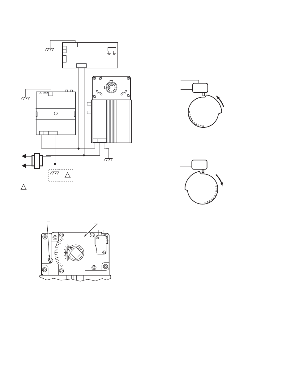
Fig. 10. Power wiring for multiple controllers.
Fig. 11. 201052 Auxiliary Switch mounted on W7751H.
NOTES:
—
If a range stop pin is used, it must be pointing
inward toward the shaft (see Fig. 11) to allow
clearance for the auxiliary switch.
—
Each switch is independently adjustable in two-
degree increments to any point within the travel of
the actuator. Switches have a fixed differential of
approximately three angular degrees.
PROCEDURE
1. Determine desired switching action (i.e, if switch
energizing is to occur during CW or CCW rotation). With
switch cam as shown in Fig. 12, the normally closed
contact opens in CCW rotation. The normally open
contact closes. Conversely, with switch cam as shown
in Fig. 13, the normally closed contact opens during CW
rotation and the normally open contact closes.
Fig. 12. Switching configuration for CCW rotation
(top view).
Fig. 13. Switching configuration for CW rotation
(top view).
2. Align switch hub with actuator set screws. Mount switch
on actuator and tighten the three captive screws.
3. Connect controller with laptop PC. To do this, the
controller on the W7751H must be wired, powered, and
connected to the portable PC via the SLTA. The SLTA
connects to the controller on the W7751H via Network
Access Jack on the T7770 Wall Module or by B-Port on
the Q7750A Zone Manager. From E-Vision Software,
drive the W7751H actuator and halt the motion at the
desired position for switch operation.
NOTE: When installed, angular position indicator on
the switch face moves from 90 to 0 degrees
during CCW motion and from 0 to 90 degrees
during CW motion.
4. Once finished programming, disconnect the portable
PC.
5. With a screwdriver, move the cam inside the switch
assembly to the appropriate position, remembering cam
travel direction for switching purposes (see Fig. 14)
when turning switch on or off. Monitor switch closure
with ohmmeter for a continuity check. Normally closed
contact should measure zero ohms and normally open
contact should measure infinite ohms when switch is not
activated. The opposite is true when switch is activated.
M10524A
28
W7751B
W7751H OR J
24
VAC
120/240
VAC
TRANSFORMER
EARTH
GROUND
EARTH
GROUND
1 2 3 4
1 2 3
9 10
W7751D,F
32
EARTH
GROUND
EARTH
GROUND
1 IF THE W7751 CONTROLLER IS USED IN UL 1995 EQUIPMENT AND THE
PRIMARY POWER IS MORE THAN 150 VOLTS, GROUND ONE SIDE
OF TRANSFORMER SECONDARY.
1
24V
COM
24V
COM
24V
COM
N
C
N
O
COM
RANGE STOP PIN
POINTED TOWARD
SHAFT
201052 AUXILARY
SWITCH
0
15
30
45
60
75
90
M10005
COM
NO
NC
M2160
CCW
COM
NO
NC
M2161
CW