A. chimney requirements, Table 8.1 – Heat & Glo Fireplace HEAT & GLO PIER-40 User Manual
Page 25
25
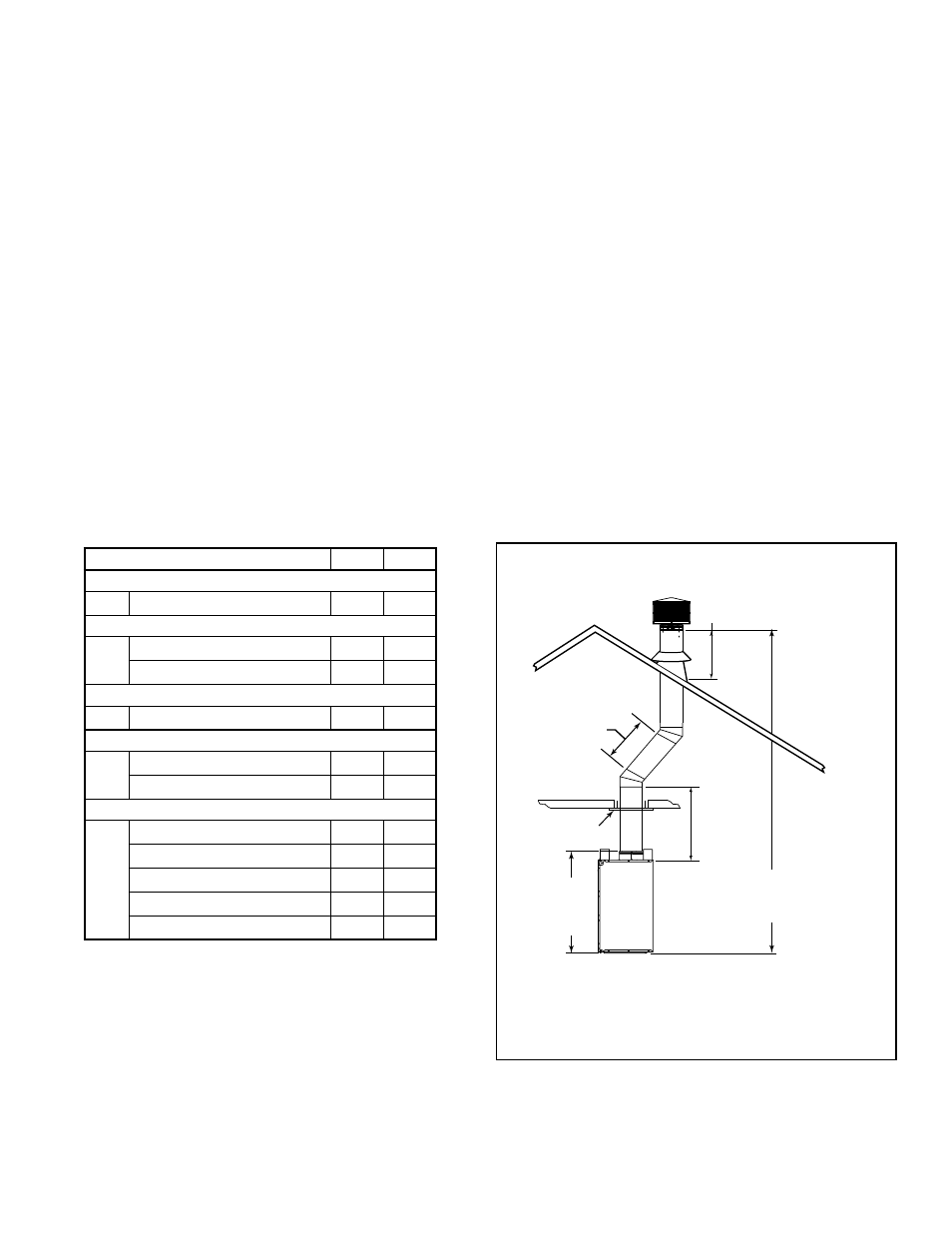
A. Chimney Requirements
Measure vertical distances from the base of the fireplace
as shown in Figure 8.2.
20 ft (6.10 m) max.
pipe between an
offset & return
Ceiling Firestop
35 ft (10.7 m)
max. straight
unsupported
chimney height
16.5 ft (4.04 m) min. height/single offset-return
20 ft. (5.03 m) min. height/double offset-return
90 ft (27.43 m) max. height
6 ft (1.83 m) max.
unsupported chimney
above roof
44 in.
(1118 mm)
Effective
Height
Figure 8.2 Chimney Requirements
Table 8.1
• Minimum overall straight height
14
(4.27 m)
• Minimum height with offset/return
16.5 ft
(5.03 m)
• Maximum height
90 ft
(27.43 m)
• Maximum chimney length between an offset
and return
20 ft
(6.1 m)
• Maximum distance between chimney
stabilizers
35 ft
(10.67 m)
• Double offset/return minimum height
20 ft
(6.1 m)
• Maximum unsupported chimney length
between the offset and return
6 ft
(1.83 m)
• Maximum unsupported chimney height above
the fireplace
35 ft
(10.67 m)
• Maximum unsupported chimney above roof
6 ft
(1.83 m)
WARNING! Risk of Fire! You must maintain 2 in. (51
mm) air space clearance to insulation and other combus-
tible materials around the chimney system. Failure to do
so may cause overheating and fire.
Determine the chimney components needed to complete
your particular installation:
• Measure the total vertical height of the fireplace
installation from the base of the fireplace assembly to
the approximate location of the bottom of the termination
cap.
• Subtract the effective height of the fireplace assembly
(see Figure 8.2) from the total vertical height to determine
the overall height of the chimney installation.
• Create a schematic for your application similar to Figure
8.2 showing components required (referring to Table
8.1). Figure 8.1 identifies those components and where
used.
• Install a ceiling firestop whenever the chimney penetrates
a floor/ceiling.
NOTICE:
A maximum of two pairs of offsets and returns
may be used.
CAUTION!
Risk of Fire and/or Asphyxiation! DO
NOT connect this fireplace to a chimney flue servicing
another appliance.
DO NOT connect to any air distribu-
tion duct or system. These actions could cause over-
heating/fire in the chimney flue, or release of exhaust
fumes into the living areas.
Heat & Glo • BAY-40, PIER-40 • 34977 • Rev AE • 05/07/13
HEIGHT OF CHIMNEY COMPONENTS
in.
mm
Chimney Stabilizer
SL11
4-3/4
121
Ceiling Firestops
FS538
0
0
FS540
0
0
Offsets/Returns
SL1130
18
457
Roof Flashing
RF570
0
0
RF571
0
0
Chimney Sections*
SL1106
4-3/4
121
SL1112
10-3/4
273
SL1118
16-3/4
425
SL1136
34-3/4
883
SL1148
46-3/4
1187
* Dimensions reflect effective height.