E. install outside air kit – Heat & Glo Fireplace HEAT & GLO PIER-40 User Manual
Page 23
23
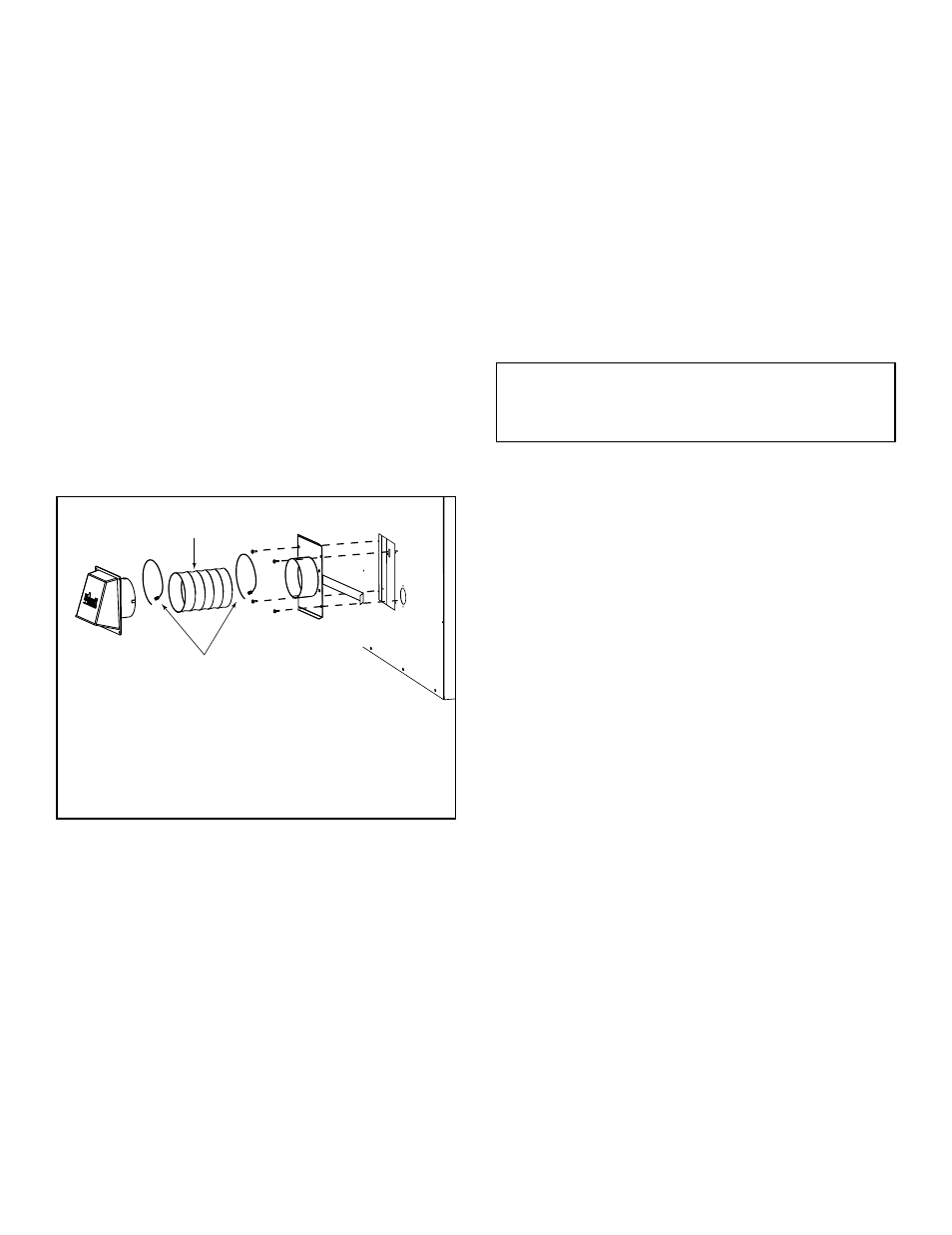
Outside Air
Hood
Outside Air
Plate
Assembly
2 Wire Ties
Flexible Duct
(not supplied)
• Hearth & Home Technologies Inc recommends using
UL181 Class 0 or Class I rigid or flexible ducting.
• Secure flex duct with metal tape, screws or wire ties.
Figure 7.5 Typical Outside Air Installation (BAY-40 will be in-
stalled from the bottom of the fireplace)
E. Install Outside Air Kit
• Keep duct runs short and straight to minimize restriction.
A small dip is acceptable for a cold air trap.
• The outside air kit must be installed on the left hand side
of the fireplace.
• Locate the outside air hood in a clear area, preferably
into prevailing wind during the heating season. Refer to
Figure 5.2.
• Install as shown in Figures 7.3 - 7.5.
• The air duct may be run vertically.
• The outside air hood must be at least 3 ft (.91 m) below
the top of the uppermost chimney section.
CAUTION!
Risk of Fire or Asphyxiation! DO NOT
draw outside combustion air from wall, floor or ceiling
cavity, or enclosed spaces such as an attic or garage.
•
DO NOT place outside air hood close to exhaust
vents or chimneys. Fumes or odor could be drawn
into the room through the fireplace.
• Locate outside air inlet to prevent blockage from
leaves, snow/ice, or other debris. Blockages could
cause combustion air starvation.
AK17 Installation (BAY-40)
• Remove the cover plate from the bottom of the fireplace
and replace it with outside air plate assembly using
existing screws.
• Mark and cut out a 4 1/2 in. (114 mm) diameter hole in the
building side for air entry. This hole should allow for some
framing (two sides) so the outside air hood assembly may
be nailed into position, flush with building’s outside.
• Secure flexible duct (not supplied) to the plate
assembly.
• Feed duct through hole to the outside, fasten to the hood
assembly.
• Fasten outside air hood assembly to the structure with
screws.
Note: To guard against significant cold air infiltration
through duct or other parts of system, check for light leaks
with a flashlight and seal these with duct tape and/or
insulation.
AK14/AK18 Installation (PIER-40)
• The hinge will be toward the front of the fireplace.
• Insert the narrow end of the handle into the upper slot.
• Pivot the handle in the slot toward the hinge.
• Remove the cover plate or knockout from the side of the
fireplace and discard. Remove the semi-perforated piece
of insulation covering the opening (insulated fireplaces
only).
• Partly open the air kit door and insert the handle into the
appropriate hole in the side column of the fireplace. The
hinge on the door assembly should be located toward
the front of the fireplace. If the hinge and the handle are
not positioned in this manner, the door will not function
correctly.
• Attach the door assembly to the fireplace using the
screws provided.
• Check operation by pulling the handle out to open and
pushing it in to close.
• Mark and cut out a 4 1/2 in. (114 mm) hole in the building
side for air entry. This hole should allow some framing
(two sides) so the 4 in. (102 mm) diameter inlet tube
assembly may be fastened properly.
• Assemble flexible duct (not supplied) between the door
assembly and the inlet tube assembly. Secure it in
position with the supplied wire ties.
Heat & Glo • BAY-40, PIER-40 • 34977 • Rev AE • 05/07/13