F. step-by-step installation of the system, Gas line, Installation instructions – Hearth and Home Technologies GBI25 User Manual
Page 6: Venting requirements, Gbi25 series b-vent gas fired fireplace insert
26678 Rev H
6
02-02
GBI25 SERIES B-VENT GAS FIRED FIREPLACE INSERT
F. STEP-BY-STEP INSTALLATION OF THE SYSTEM
WARNING!
Before starting, do the following:
1.
Wear gloves and safety glasses for protection.
2.
Keep hand tools in good contition. Sharpen cutting edges and make sure tool handles are secure.
3.
Always maintain the minimum air space required to the enclosure to prevent fire.
WARNING!
This appliance is equipped with a safety control system designed to protect against improper venting of com-
bustion products. Operation of this appliance when not connected to a properly installed and maintained venting
system, or tampering with a vent safety shut-off system can result in carbon monoxide (CO) poisoning and
possible death.
1. VENTING REQUIREMENTS
A flue liner from the outlet of the draft hood to the roof
termination is required. This appliance is required to
be connected to a listed 4 diameter, stainless steel
or aluminum flexible gas vent liner with a top
termination. A 4 B-Vent or listed 4 rigid single wall
gas vent may also be used.
Before attempting to run your flue liner, you must make
sure that it will pass through the existing damper area;
this is best done with a flexible liner. In a zero clearance
(factory built) fireplace, the existing damper must be
removed or locked out of the way in the open position.
For masonry fireplaces, if the damper will not allow
the passage or a 4 flex, do not proceed without
consulting a local mason on how to remove or alter
the damper without risk of structural damage or
leakage.
A minimum vertical venting height of 9 feet above the
base of the appliance must be maintined. The
horizontal run must not exceed 50% of the vertical
height. Maximum vertical venting height is 40 above
the base of the appliance. The vent termination must
be in accordance with its respective listing and
manufacturers instructions.
Install 4 flue liner down through the chimney. When
using flexible liner, use caution around the offsets so
as not to rupture the liner. Measure up 16 from the
existing fireplace bottom and leave hanging in
fireplace.
2. GAS LINE INSTALLATION
A gas line must run into the existing woodburning
fireplace, for either a factory built or masonry fireplace.
If it is a factory built fireplace, the gas line should be
brought into the fireplace through the gas knockouts
provided.
Note:
The appliance and its manual shutoff valve must
be disconnected from the gas supply piping system
during any pressure testing of that system at test pres-
sures in excess of 1/2 psi (3.5 kPa). The appliance must
be isolated from the gas supply piping system by clos-
ing the manual shutoff valve during any pressure test-
ing of the gas supply piping system at test pressures
equal to or less than 1/2 psi (3.5 kPa).
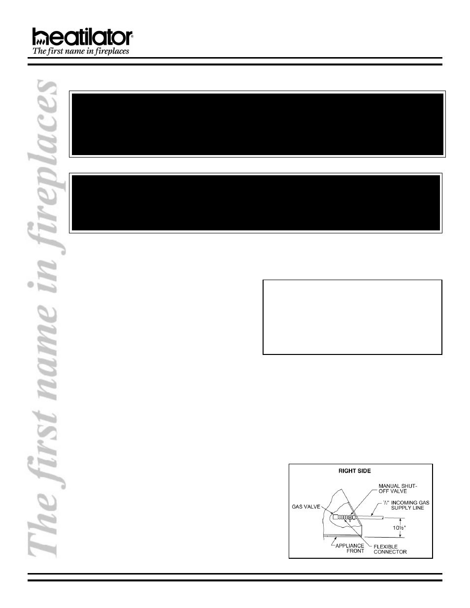
It is recommended that 1/2 inside diameter black
pipe be run into the fireplace through the right side. If
the existing fireplace already has gas run to it, but
through the left side, it is recommended that the gas
be rerouted to the right side. See Figure 1.
Place an elbow at the end of the black pipe so that it
runs perpendicular to the face. A 1/3 flare adapter
(not supplied) is necessary to connect the flex line
(supplied) to the black pipe.
Check for leaks using a soap and water solution or a
leak detector.
Figure 1 - Gas Line Installation