Mounting thermostat – Honeywell Chronotherm IV T8601D User Manual
Page 3
T8601D CHRONOTHERM® IV DELUXE PROGRAMMABLE THERMOSTATS
3
69-1410—2
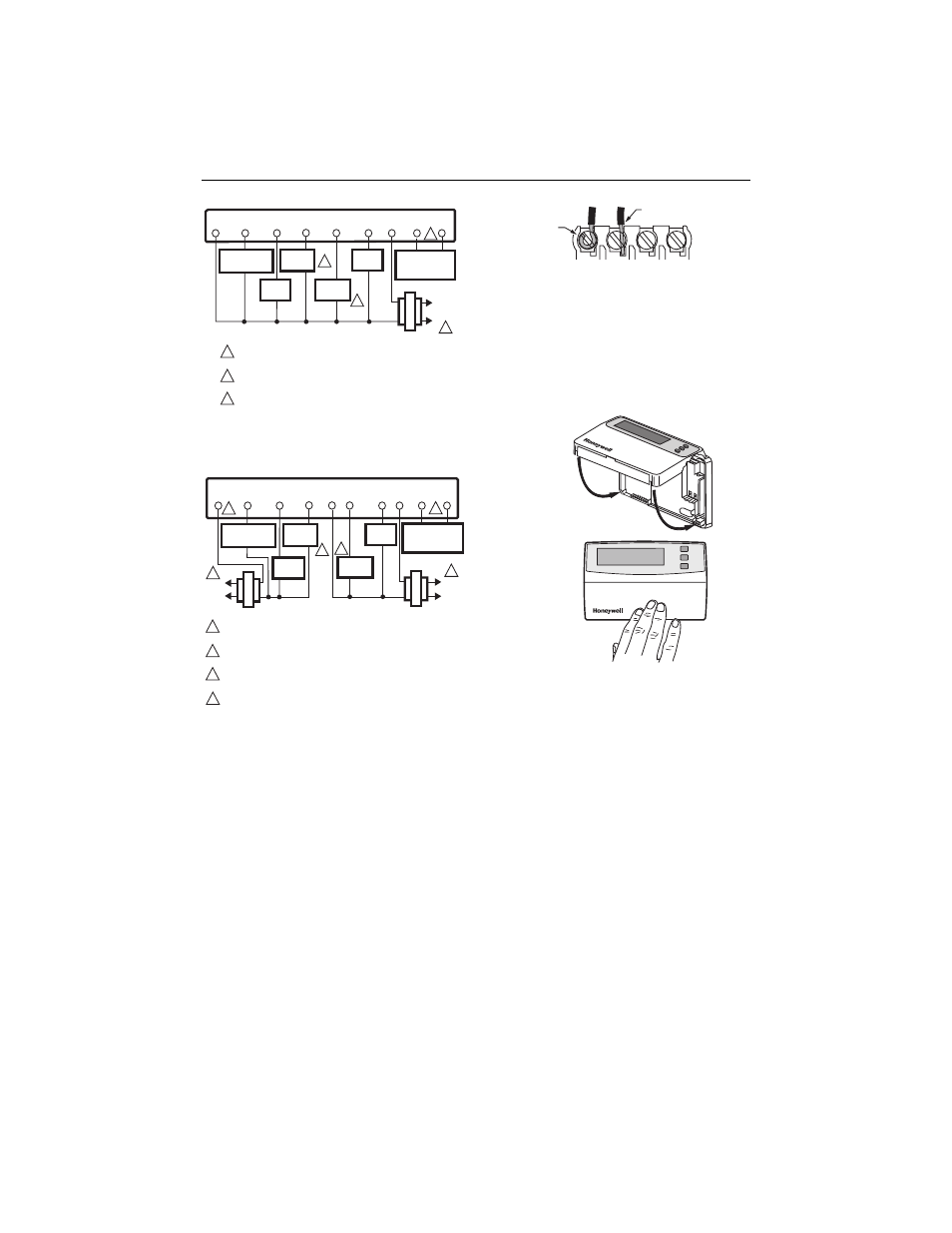
Fig. 4. Typical hookup in heat and cool
system with one transformer.
Fig. 5. Typical hookup in heat and cool
system with two transformers.
Fig. 6. Proper wiring technique.
Mounting Thermostat
1. Engage tabs at the top of the thermostat and wall-
plate. See Fig. 7.
2. Press lower edge of case to close and latch.
NOTES: To remove the thermostat from the wall, first pull
out at the bottom of the thermostat; remove top
last.
Fig. 7. Mounting thermostat on wallplate.
L1
(HOT)
L2
M10353
FAN
RELAY
Y
G
THERMOSTAT
C
HEAT
RELAY
R
W
COMPRESSOR
CONTACTOR
TRANSFORMER
B
HEAT
DAMPER
COOL
DAMPER
O
1
POWER SUPPLY. PROVIDE DISCONNECT MEANS AND OVERLOAD
PROTECTION AS REQUIRED.
CAN BE USED FOR CHANGEOVER VALVE ON SINGLE-STAGE HEAT
PUMP SYSTEMS.
AVAILABLE ON SELECT MODELS. OT WIRES MUST HAVE A
SEPARATE CABLE FROM THE THERMOSTAT CABLE.
2
2
2
1
3
OT
OT
OUTDOOR
TEMPERATURE
SENSOR
3
L1
(HOT)
L2
M10354
FAN
RELAY
Y
G
THERMOSTAT
RC
HEAT
RELAY
R
W
L1
(HOT)
L2
COMPRESSOR
CONTACTOR
HEATING TRANSFORMER
COOLING TRANSFORMER
B
C
HEAT
DAMPER
COOL
DAMPER
O
2
1
POWER SUPPLY. PROVIDE DISCONNECT MEANS AND OVERLOAD
PROTECTION AS REQUIRED.
JUMPER RC TERMINAL TO R TERMINAL WHEN INSTALLED ON A
ONE TRANSFORMER SYSTEM.
CAN BE USED FOR CHANGEOVER VALVE ON SINGLE-STAGE HEAT
PUMP SYSTEMS.
AVAILABLE ON SELECT MODELS. OT WIRES MUST HAVE A
SEPARATE CABLE FROM THE THERMOSTAT CABLE.
2
3
3
1
1
3
4
OT
OT
OUTDOOR
TEMPERATURE
SENSOR
4
M4826
FOR WRAPAROUND
INSERTION STRIP
7/16 IN. (11 MM).
FOR STRAIGHT INSERTION
STRIP 5/16 IN. (8 MM).
M14628
PRESS LOWER
EDGE OF CASE
TO LATCH.
ENGAGE TABS
AT TOP OF
THERMOSTAT
AND WALLPLATE.
A.
B.