Tractor preparation, Subframe installation, Subframe i n s t a l l a t i o n – HONDA QH4000 User Manual
Page 7
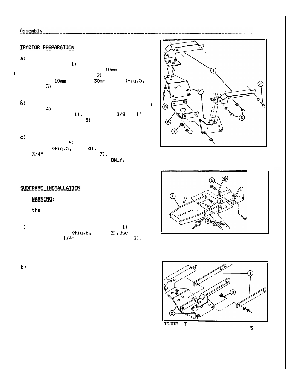
Loosely a t t a c h t h e f r o n t support brackets
( f i g . 5 , i t e m
t o t h e t r a c t o r frame.
For
each bracket, use one
x
1.25
x
25mm b o l t ( f i g . 5 , i t e m
w i t h lockwasher,
and two
x
1.25
x
b o l t s
i t e m .
w i t h lockwashers f o r each bracket.
Do
not t i g h t e n yet.
Loosely a t t a c h t h e a t t a c h i n g p l a t e s ( f i g . 5
i t e m
t o t h e f r o n t support brackets
(fig.5,
i t e m
Use
three
x
b o l t s ( f i g . 5 , i t e m
w i t h lockwashers
f o r each p l a t e s .
Do
not t i g h t e n yet.
Loosely i n s t a l l t h e reinforcement p l a t e
( f i g . 5 , i t e m
between t h e two a t t a c h i n g
p l a t e s
i t e m
Use
two 5/16" x
b o l t s ( f i g . 5 , item
lockwashers
and n u t s
I N THE FRONT HOLES
I n s t a l l
t h e b o l t s heads and
lockwashers from
t h e i n s i d e w i t h t h e nut on t h e outside
as shown.
Do
n o t t i g h t e n yet.
To avoid i n j u r y ,
park t h e
t r a c t o r
on
a l e v e l surface, t u r n o f f
engine, remove t h e key and s e t t h e
p a r k i n g brake.
a
I n s t a l l male h i t c h (fig.6, i t e m
i n t h e
p i v o t bracket
item
f o u r
7/16"
x
1
b o l t s ( f i g . 6 , i t e m
lockwashers and nuts. I n s t a l l t h e b o l t s
from t h e i n s i d e
as
shown, and t i g h t e n
them securely.
P o s i t i o n t h e subframe assembly under
t h e t r a c t o r .
I n s e r t t h e r e a r of the
assembly between t h e wheels on t h e
r i g h t hand s i d e of
t h e t r a c t o r , and
then
p u l l
it
forward.
OM
0149
.
FIGURE
5
FIGURE
6