HONDA QH4000 User Manual
Page 6
Thread the adjustment f o r k ( f i g . 2 , i t e m
i n t o t h e end of t h e push arm (fig.2,
i t e m
Adjust t h e o v e r a l l l e n g t h of push
arm assembly t o
32
13/16".
Place an
11/16" f latwasher and a bent
r e t a i n e r p l a t e
i t e m
on t h e
x
4" b o l t ( f i g . 2 , i t e m
I n s e r t t h e b o l t i n t o t h e l e v e r
as
shown.
Place another
bent r e t a i n e r p l a t e and
flatwasher on t h e b o l t ,
and secure
it
l o o s e l y w i t h a lockwasher and nut.
I n s t a l l
a f l a n g e bearing
i t e m
i n t o each l i f t support bracket ( f i g . 3 ,
i t e m
from t h e i n s i d e .
I n s e r t t h e
l i f t arm (fig.3, i t e m
through
t h e bearing i n t h e r i g h t hand
l i f t
support bracket.
Put a tube spacer
( f i g . 3 , item
on t h e arm,
and then
i n s e r t t h e arm through t h e
l i f t l e v e r
(under t h e
.
I n s e r t t h e arm through another tube
spacer, and then through t h e l e f t hand
l i f t support bracket bearing.
The end
of t h e arm should p r o t r u d e
2
beyond
the bearing.
P o s i t i o n t h e subframe channel
i t e m
i n l i n e w i t h subframe f l a t b a r s
( f i g .
1, i t e m
and securely t i g h t e n
b o l t s
i t e m
7 and
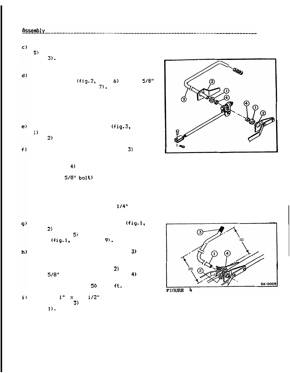
Rotate t h e
l i f t arm ( f i g . 4 , i t e m
so
t h a t i t s handle i s p a r a l l e l t o t h e
ground, and block i n t h a t p o s i t i o n . Set
t h e
l i f t
l e v e r ( f i g . 4 , i t e m
so that
t h e
x
4" b o l t ( f i g . 4 , i t e m
is
perpendicular t o t h e ground,
and then
t i g h t e n t h e b o l t t o
l b s .
I n s t a l l
4
p l a s t i c handle
(fig.4, i t e m
on
l i f t arm ( f i g . 4 ,
i t e m
4
FIGURE
3