D. test procedure, D. test procedure -20 – Honeywell KA 54 User Manual
Page 46
N
KRA 405B RADAR ALTIMETER INSTALLATION MANUAL
Page 2-20
006-10536-0010 Rev. 10
Oct/2005
An antenna fault will be detected when its cable is ter-
minated into a 50 ohm load and the indicator needle will
stow behind the mask. Re-bond the antenna if the point-
er is now stowed.
If the indicator pointer still does not stow, this in-
dicates an RF cable or connector problem. Remove both
cables at the antenna and terminate one of them with a
50 ohm RF load. Remove the other cable at the R/T end
and terminate with a 50 ohm RF load. The indicator nee-
dle should stow behind the mask.
h.
Repeat this test for the other cable. A fault here can
be addressed by following the suggestions in
D.
TEST PROCEDURE
KRA 405B Radar Altimeter Post Installation Test Procedures using
1000 Foot Delay Line.
(1)
Purpose of Test.
This test simulates an actual altitude of 1000 feet AGL with
various return signal strengths. Low power output, poor coax
cables, poor connectors and poor R/T performance can be found
using this method.
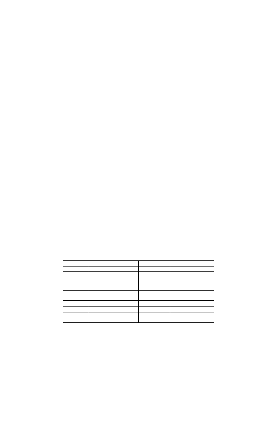
(2)
Required Equipment
The items listed below or their electrical equivalent, may be
used to conduct the tests in this section.
QUANTITY
DESCRIPTION
MANUFACTURER
MANU. PART NUMBER
1
1000 ft Delayline
Teledyne
M7421B
1
Attenuator Variable
4-8 GHz 0-40 dB
Narda
794-FM
2
Attenuator Fixed
3-6 GHz 20 dB
Narda
773-20
2
Adapter N
F
to SMA
P/N 030-00123-0000
Americon
2082-2300
2
Adapter N
M
to TNC
F
Amphenol
78800
1
Adapter N
M
to TNC
M
Amphenol
78875
1
6 ft RG 393/U with TNC
M
con-
nector