C. antennas, C. antennas -9, Table 2-1 – Honeywell KA 54 User Manual
Page 35: Tso certified antennas -9
N
KRA 405B RADAR ALTIMETER INSTALLATION MANUAL
Page 2-9
006-10536-0010 Rev. 10
Oct/2005
(3)
Make certain that clearance is available between units so that
normal vibration does not cause the unit to strike adjacent
equipment cases.
(4)
Allow clearance behind the unit for installation of the cables
and connectors.
(5)
If an instrument hole that meets the installation requirements
is not available, cut a 3 inch ATI hole per
. The unit may be mounted in
front of or behind the panel. Secure the unit with mounting
ring provided and four (4) 1/2 inch long 6-32 instrument
screws.
C.
ANTENNAS
The KRA 405B Radar Altimeter System requires two antennas for a
single system installation. Since the system is CW, one antenna is
used to transmit the signal and the other is used to receive the
reflected signal.
In order to meet the requirements of TSO C87/ETSO-2C87, the KRA 405B
Radar Altimeter System must use TSO certified antennas with the
.
Recommended antennas are listed in
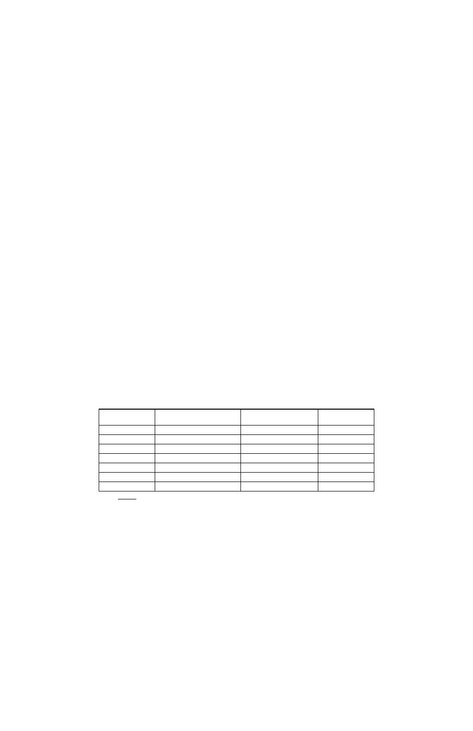
TABLE 2-1 TSO CERTIFIED ANTENNAS
below:
NOTE:
Variances between the S67-2002 and S67-2002-4 are depicted in
FIGURE 2-12 HONEYWELL GT 7003586 (SENSOR SYSTEMS TYPE S67-2002-
technical information.
TABLE 2-1 TSO CERTIFIED ANTENNAS
MANUFACTURER
PART NUMBER
HONEYWELL DESIGNATION
MANUFACTURER
FIGURE NUMBER
DMPN 3-3A
KA 54
Dorne and Margolin
2-8
DMPN 3-4A
KA 54
Dorne and Margolin
2-10
AD43013-1
KA 54
UB Corporation
2-9
01-34-04531
KA 54
Comant Industries
2-9
S67-2002
KA 54A (white or black
Sensor Systems Inc.
2-11
DMPN 19-2-1
KA 54A
Dorne and Margolin
2-11
S67-2002-4
KA 54
Sensor Systems Inc.
2-12