Wiring, Caution, Wiring wall modules – Honeywell ZIO TR75 User Manual
Page 3
ZIO
®
/ZIO PLUS LCD WALL MODULES
3
62-0271—07
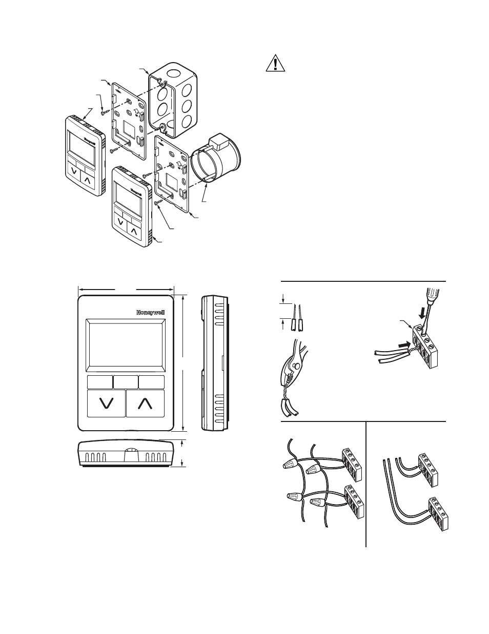
Fig. 3. Mounting on standard utility conduit box or
60 mm wall outlet box.
Fig. 4. LCD Wall Module dimensions in inches (mm).
Wiring
The LCD wall module is shipped with its mounting plate
(subbase) separate from the module. All terminal connections
can be made to the backside of the module. There are no field
adjustable/replaceable components inside the module.
Attach the wires from the programmable controller and
network to the appropriate wall module terminals, as indicated
CAUTION
Improper Electrical Contact Hazard.
Screw-type terminal blocks are designed to accept
no more than one 18 AWG (0.82 sq. mm)
conductor.
Connect multiple wires that are 18 AWG (0.82 sq. mm)
with a wire nut. Include a pigtail with this wire group
and attach the pigtail to the individual terminal block.
Wiring Wall Modules
Wire the terminal block shown in Fig. 6 as follows:
1. For single wires, strip 3/16 in. (5 mm); for multiple wires
going into one terminal, strip 1/2 in. (13 mm) insulation
from the conductor. See Fig. 5 for wiring multiple Zios.
2. Insert the wire in the required terminal location and
tighten the screw to complete the termination.
3. Review and verify the terminal connection wiring
illustrated in Fig. 6.
NOTE: The recommended wire size for the network bus
and S-BUS is Level IV, 22 AWG (0.34 sq. mm) ple-
num or non-plenum rated, unshielded, twisted
pair, solid conductor wire. However, larger gauge
standard thermostat wiring will also work for
runs up to 100 feet.
Fig. 5. Options for Wiring Multiple Zios.
M27346
STANDARD UTILITY
CONDUIT BOX
SUBBASE
NO. 6 SCREW
60 mm WALL
OUTLET BOX
SUBBASE
3.5 mm SCREW
WALL MODULE
WALL
MODULE
3 5/16 (84)
4 5/8
(117)
15/16
(24)
M27347
TO SPYDER
TWO WIRES INTO ONE TERMINAL
DAISY-CHAINING MULTIPLE ZIOS
HOME RUNNING MULTIPLE ZIOS
TO SPYDER
TO ZIO
1/2
(13)
STRIP 1/2 IN.
(13MM) FROM
WIRES TO BE
ATTACHED AT
ONE TERMINAL.
1.
2.
TWIST WIRES
TOGETHER
WITH PLIERS
(A MINIMUM OF
THREE TURNS).
3.
CUT TWISTED END OF WIRES TO
3/16 IN. (5 MM) BEFORE INSERTING
INTO TERMINAL AND TIGHTENING
SCREW. THEN PULL ON EACH WIRE
IN ALL TERMINALS TO CHECK FOR
GOOD MECHANICAL CONNECTION.
M27348
WALL MODULE
TERMINALS
MAX WIRE RUN FROM SPYDER
TO FARTHEST ZIO IS 200FT.
MAX WIRE RUN FOR EACH
HOME RUN IS 200FT.