Power up, Fig. 6 a, Fig. 6 – Honeywell ZIO TR75 User Manual
Page 4: Setting the wall module bus address dial, Attaching the wall module to the subbase, Removing the wall module from subbase, Automation and control solutions, Please load
ZIO
®
/ZIO PLUS LCD WALL MODULES
Automation and Control Solutions
Honeywell International Inc.
1985 Douglas Drive North
Golden Valley, MN 55422
customer.honeywell.com
® U.S. Registered Trademark
© 2012 Honeywell International Inc.
62-0271—07 M.S. Rev. 01-12
Printed in United States
Fig. 6. Terminal connections, Wall Module bus address
dial, and TR70-H address dial (rear view of LCD wall
module).
Setting the Wall Module Bus Address Dial
For the TR70, ensure that the wall module bus address dial is
set to 1. For the TR71 or TR75 models, set the address to any
number from 0 to 9. (A setting of 0 on Zio is equal to 10 in the
Configuration Tool, so if the Zio is set to 0, set the address to
10 in the Configuration Tool.) Address must be different for
each device on the Sylk bus. Use a thin blade screwdriver to
turn the dial arrow. The address on the wall module must
match the address in the tool. A maximum of four Zios may
be wired on a single Sylk bus, with no more than one TR70
per bus.
Attaching the Wall Module to the Subbase
When all wiring is complete, press the LCD wall module
straight down onto the subbase until it snaps into place.
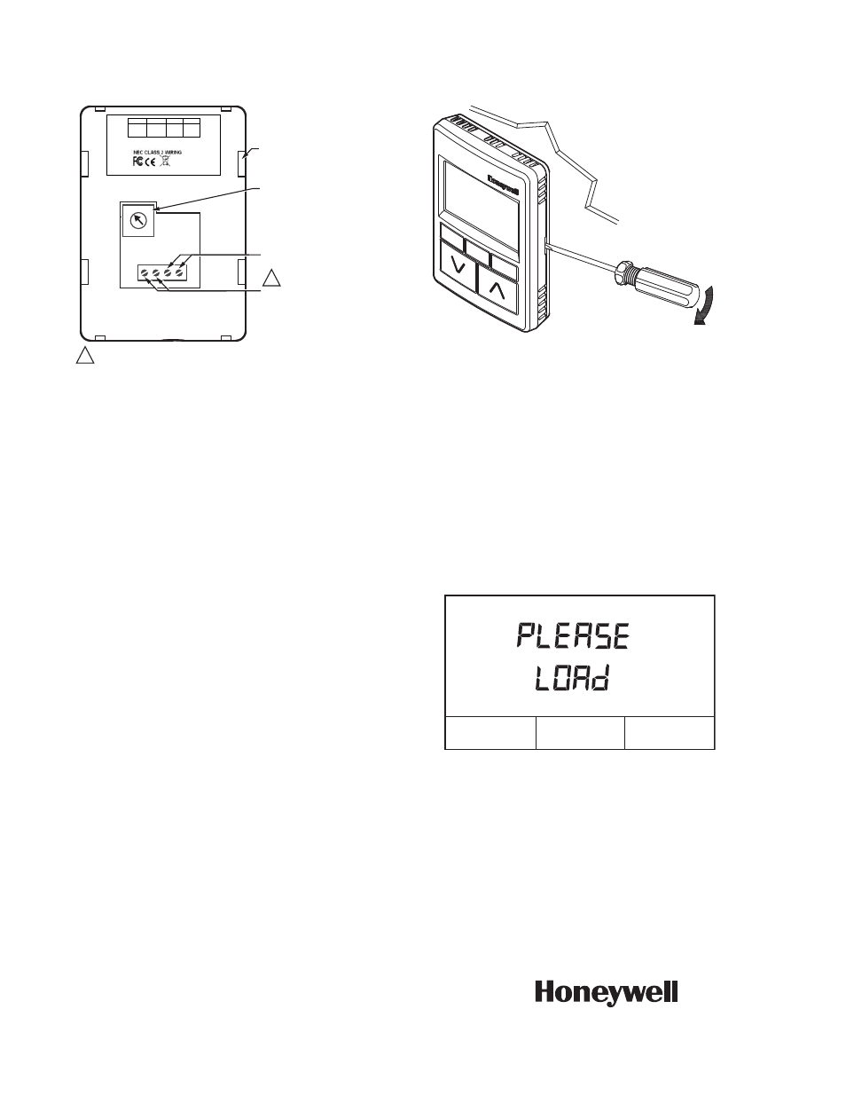
Removing the Wall Module from Subbase
To remove the wall module from its subbase:
1. Insert a thin, flat-blade screwdriver into the slot on the
right side of the wall module (see Fig. 7).
2. Pull the screwdriver toward you to release the right side
of the wall module from the subbase.
3. Pull the wall module out and away from the subbase.
Fig. 7. Removing Wall Module from Subbase.
POWER UP
After the wall module is properly wired to the controller, it will
power up. Upon initial power up, the wall module LCD panel
displays the phrase,
“PLEASE LOAd”
(see Fig. 8). This
phrase alternates with bus address, model and version
number (TR71 and TR75 only), and any onboard sensor
display, such as temperature, humidity, etc.
Refer to the Zio/Zio Plus LCD Wall Modules Operating Guide
(Form 63-2719) to configure and load the desired user
interface and parameters into the wall module.
Fig. 8. Wall Module LCD display at initial power up.
ComfortPoint™ is a trademark of Honeywell International Inc.
L
ON
M
ARK
® is a trademark of the LonMark Association.
BACnet® is a trademark of BACnet International.
Sylk® is a trademark of Honeywell International Inc.
Zio® is a trademark of Honeywell International Inc.
M27349
SLOTS FOR SUBBASE
LOCKING TABS (X4)
0
1 2 3
4
9
8 7 6
5
WALL MODULE BUS
ADDRESS DIAL
(DEFAULT SETTING = 1)
S-BUS PROGRAMMABLE
CONTROLLER CONNECTION
NETWORK BUS
CONNECTION
EACH OF THE TWO WIRE CONNECTIONS FOR THE S-BUS AND NETWORK
BUS TERMINALS ARE POLARITY INSENSITIVE.
1 2 3 4
1
1
50028668-XXX
4
3
2
1
S-BUS
S-BUS
NET-2
(optional)
NET-1
(optional)
TR70-H
YY WK
HONEYWELL
PATENT PENDING
GOLDEN VALLEY,MN
ASSEMBLED IN MEXICO
WALL
PULL THE
SCREWDRIVER
TOWARD YOU
M27350
M27351A