Step 8. wiring the fireplace – Hearth and Home Technologies Everest User Manual
Page 24
Heat & Glo • Everest • 750-900 Rev. o • 10/08
24
Step 8. Wiring the Fireplace
NOTE: Electrical wiring must be installed by a licensed
electrician.
CAUTION: DISCONNECT REMOTE CONTROLS IF
YOU ARE ABSENT FOR EXTENDED TIME PERIODS.
THIS WILL PREVENT ACCIDENTAL FIREPLACE
OPERATION.
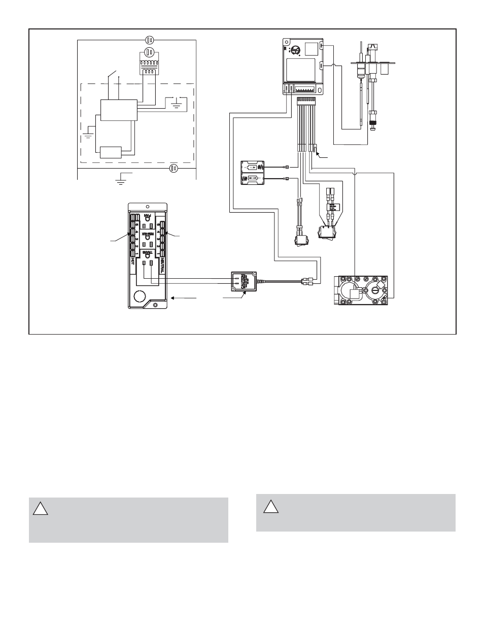
Intermittent Pilot Ignition (IPI) Wiring
Appliance Requirements
This appliance requires that 110-120 VAC be wired to the
factory installed junction box. Maintain correct polarity when
wiring the junction box.
!
!
Figure 23. Intermittent Pilot Ignition (IPI) Wiring Diagram
IGNITION MODULE
3 VAC
TRANSFORMER
3 VAC
GRN
ORG
BA
TTER
Y
BACK
UP
SWITCH
INTERMITTENT
PILOT
IGNITOR
IGNITION
MODULE
(3V)
ON/OFF
WALL
SWITCH
LOW VOLTAGE
PLUG-IN
3V TRANSFORMER
NEUTRAL
HOT
GROUND
FLAME SPARKER/
SENSOR
REMOTE
CONTROL
SEE NOTE 1
ORG
WHT
VALVE
PIGGYBACK
ON/OFF
SWITCH
BLACK -
REMOVE BATTERIES
WHEN 3V
TRANFORMER
IS USED
BATTERY
PACK
RED +
WHITE WIRE
CAN BE
PLUGGED
INTO ANY
OF #1-#5
LOCATIONS
ON THE
NEUTRAL SIDE
BLACK WIRE CAN BE
PLUGGED INTO ANY OF
#1 - #5 LOCATIONS
ON THE HOT SIDE
BRN
BRN
VALVE
PLUG IN
GROUND TO
FIREPLACE
CHASSIS
I
S
CAUTION: LABEL ALL WIRES PRIOR TO DISCON-
NECTION WHEN SERVICING CONTROLS. WIRING
ERRORS CAN CAUSE IMPROPER AND DANGEROUS
OPERATION. VERIFY PROPER OPERATION AFTER
SERVICING.
WARNING: DO NOT CONNECT 110-120 VAC
TO THE WALL SWITCH OR THE CONTROL
VALVE WILL BE DESTROYED.
Optional Accessories
Optional remote control kits require that 110-120 VAC be
wired to the factory installed junction box before the fi re-
place is permanently installed.
Wall Switch
Position the wall switch in the desired position on the wall.
An assembly of 18 ft of 20 AWG is provided with the fi re-
place to connect the wall switch to the appliance. Instead
of the supplied assembly, wire with a length of 25 ft or less
and a gauge of 20 AWG through 14 AWG is acceptable.
The wire needs a jacket with a temperature rating of 140º
F (60º C) or higher. At the appliance connect the wire to
the ON/OFF switch pigtails.
WARNING: DO NOT CONNECT 110-120 VAC
TO THE GAS CONTROL VALVE OR THE AP-
PLIANCE WILL MALFUNCTION AND THE
VALVE WILL BE DESTROYED
Batteries should not be placed in the battery pack while
using the 3 volt AC transformer. The transformer must be
unplugged if the battery pack is used or battery life will be
reduced.