System connection e, System connection e xample xample – Eclipse - Fujitsu Ten AVN5495 EN User Manual
Page 13
- 13 -
System connection e
System connection e
xample
xample
•
Never cut the insulation on the power cable or use it to power any other equipment. If the rated current
capacity of the power cable is exceeded, fire and electric shocks may result.
•
The cables should be secured with tape or similar item so it will not cause an obstruction while driving.
If they get wound around components such as the steering wheel, shifting lever or brake pedal,
accidents may result.
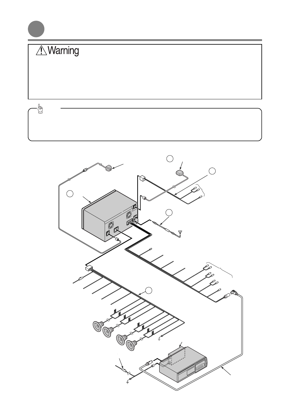
• Install and connect all of the peripheral units before connecting them to the main unit.
• Do not remove the caps of RCA jacks unless in use.
• Be sure to wrap the connection cables with plastic tape to insulate them.
Tip
DIN CABLE
(Supplied with CD changer)
Black
TO GROUND
TO BATTERY+12V
(Permanent Supply)
Yellow
POWER CONNECTOR CABLE(Supplied with CD changer)
REAR
SPEAKERS
TO VEHICLE SPEED PULSE
SIGNAL TERMINAL (Refer to page 10)
Purple/White
TO PARKING BRAKE
SIGNAL (Refer to page 11)
Red/White
TO REVERSE SIGNAL
(Refer to page 11)
Green
TO BATTERY+12V
(Permanent Supply)
Yellow
TO ACC
(Power Supply)
Red
TO HEAD LIGHT SWITCH
(Illumination(+))
Orange/White
TO POWER ANTENNA RELAY
(Supply)
Blue
TO TURN-ON LEAD OF POWER AMPLIFER
(Supply)
Blue/White
FRONT
SPEAKERS
Black
TO GROUND
INTERCONNECTING
CABLE
(Power and speaker
connector)
2
TO EXTERNAL MONITOR
FRONT
REAR
NON FADER
(remove covers when using
external amplifier)
GPS ANTENNA
8
ANTENNA EXTENSION CABLE
Be sure to use when connecting the
radio antenna to the vehicle.
4
ANTENNA
PLUG
FROM EXTERNAL VIDEO EQUIPMENT
MAIN UNIT
1
BEC104
(sold separately)
NO
CONNECTION
CH3083
(sold separately)
13P
1P
16P
13P
2P
6P
4P
INTERCONNECTING CABLE
(Video input connector)
3