5 alarm mode flowchart, Model 7003m, Operator manual – Emerson 7003M User Manual
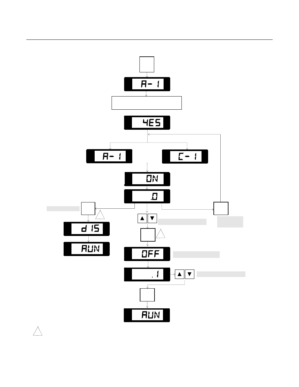
Page 43: Figure 3-5. alarm mode flowchart, Alarm/controller mode, Security access routine (see figure 3-4), Prompts "on" setpoint, Adjust alarm off setpoint, Indicates alarm is disabled
Operator Manual
748223-K
June 2002
Rosemount Analytical Inc. A Division of Emerson Process Management
Operation 3-17
Model 7003M
Figure 3-5. ALARM Mode Flowchart
ALARM/CONTROLLER MODE
SECURITY ACCESS ROUTINE
(see Figure 3-4)
ALARM1
ALARM2
%O2
°C
ALARM1
ALARM2
%O2
°C
Prompts "ON" Setpoint
ALARM1
ALARM2
%O2
°C
Displays "ON" Setpoint
Note: Alarms are disabled when instrument is received.
Alarm 2 uses identical sequence.
To Disable Alarm
ACK
Adjust Alarm OFF Setpoint
ENTER
ALARM
1
ALARM
1
Indicates Alarm
is disabled
ALARM1
ALARM2
%O2
°C
ENTER
Flashes Alarm
Configuration
Flashing
Flashes Control
Configuration
ALARM1
ALARM2
%O2
°C
ALARM1
ALARM2
%O2
°C
ALARM1
ALARM2
%O2
°C
OR
ALARM1
ALARM2
%O2
°C
ALARM1
ALARM2
%O2
°C
Prompts for OFF Setpoint
Adjust Alarm ON Setpoint
STANDARD ALARM
Change Relay
configuration
ALARM1
ALARM2
%O2
°C
ALARM1
ALARM2
%O2
°C
1
1
New values/functions will not be stored until instrument returns to RUN mode with relay activated.
1