Installation and operation, cont’d, Ipl t s series • installation 2-8, Ipl t s2 – Extron electronic IPL T S Series User Manual
Page 20: Ipl t s6
Installation and Operation, cont’d
IPL T S Series • Installation
2-8
Factory default protocol for the control interface is:
• RS-232
• 9600 baud
• no parity
• 8 data bits
• 1 stop bit
• pacing = 0 ms
• handshaking = off
Communication to an attached device can be done through the IPL T S Series
device’s default Web pages or by using Extron’s Simple Instruction Set (SIS
™
)
commands.
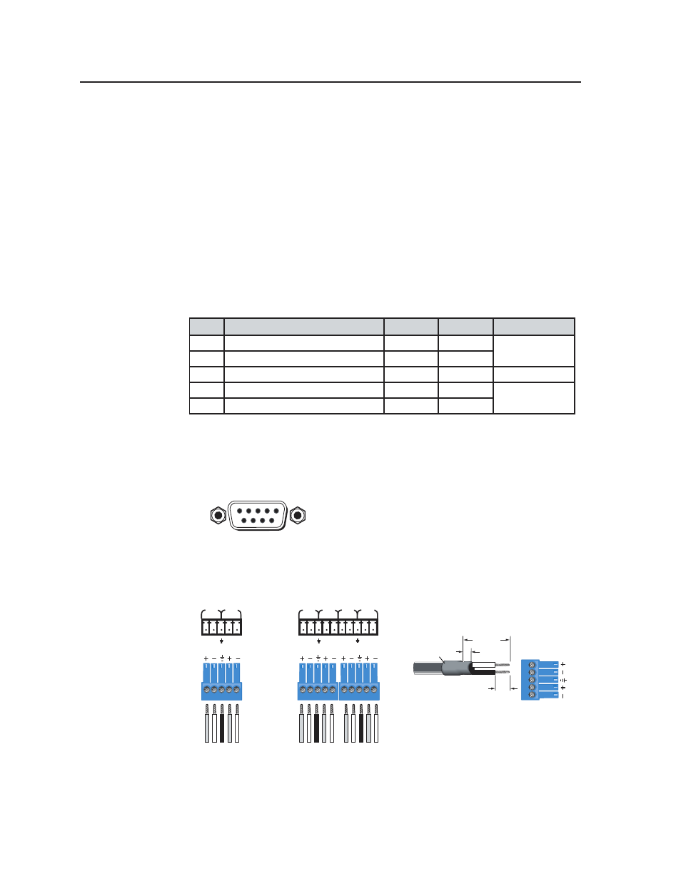
The rear panel 9-pin D connector COM ports have the following pin assignments:
Pin
Function
RS-232
RS-422
RS-485
2
Receive Data/Receive Data -
RX
RX-
Data -
(pins 2 + 3 tied)
3
Transmit Data/ Transmit Data -
TX
TX-
5
Signal Ground
GND
GND
GND
7
Request to Sent/Transmit Data +
RTS
TX+
Data +
(pins 7 + 8 tied)
8
Clear to Send/Receive Data +
CTS
TX-
N
The IPL T S1 uses RS-232 only.
When using RS-485 with the connections indicated above, Data + can connect
to either pin 7 or pin 8, and Data - can connect to either pin 2 or pin 3.
For RS-232 communication, pins 7 and 8 (RTS and CTS) are optional.
9-Pin D Connector
Pin Locations, Female
5
1
9
6
COM5
TX RX
TX RX
COM6
COM3
TX RX
TX RX
COM4
Tr
ansmit
Receiv
e
Ground
Tr
ansmit
Receiv
e
Tr
ansmit
Receiv
e
Ground
Tr
ansmit
Receiv
e
Tr
ansmit
Receiv
e
Ground
Tr
ansmit
Receiv
e
COM1
TX RX
TX RX
COM2
IPL T S2
Connectors
IPL T S6
Connectors
Heat
Shrink
1/8”
(3 mm)
7/8”
(22 mm)
3/16”
(5 mm) Max.
5-pole Captive Screw
Connector
Figure 2-10 — 5-pin captive screw assignments