Adjust rh motion control handle, Position, Adjust rh motion control handle position – Exmark Vantage VT740EKC604; User Manual
Page 43: Maintenance
Maintenance
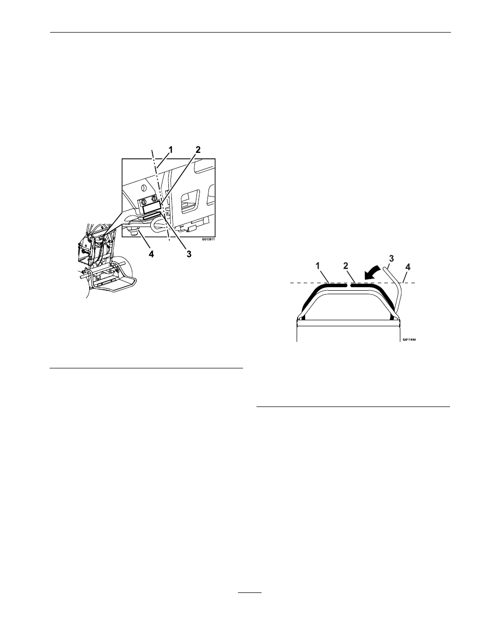
6. Check the alignment on the LH and RH neutral
switches upper and lower surfaces (reference
Figure 39). If they are not in alignment, loosen the
hardware on the lower neutral switch and adjust it
forward or rearward as necessary. Once aligned,
tighten the hardware. Check the neutral switch
alignment again as the deck is moved through the
highest and lowest cut height setting; adjust the
lower neutral switch surface if necessary.
Figure 39
1.
Alignment reference
4.
Lower neutral switch
surface
2.
Upper neutral switch
surface
5.
Hardware
3.
Switch mounting plate
7. Adjust the upper neutral switch surface left
or right if side-to-side alignment is needed.
The upper and lower switches should be as
close together as possible without touching
(approximately .06 inch (1.5 mm) gap is desirable).
The switch mounting plate can be moved up or
down to adjust the position of the lower neutral
switch.
8. Check the function of the neutral switches by
temporarily replacing the key. With the engine off,
turn the ignition switch to the “ON” position.
Locate the LCD indicator in the message display.
Raise and lower the deck.
A. If the indicator displays while moving the deck
up and down, the neutral switches have been
adjusted properly and no further adjustment
is necessary.
B. If the indicator does not stay lit while moving
the deck up and down, contact an Authorized
Service Dealer. Remove the key.
Adjust RH Motion Control
Handle Position
If the motion control levers do not align horizontally,
adjust the right side motion control lever.
Note: Adjust the horizontal alignment before the
front to back alignment.
1. Stop engine, wait for all moving parts to stop, and
remove key. Engage parking brake.
2. Push the right motion control lever down out of
locked neutral position.
3. Check if it aligns horizontally with the left motion
control lever.
Figure 40
1.
LH Motion control lever
2.
RH Motion control lever
3.
RH Motion control lever in PTO disengaged position
4.
Check the horizontal alignment here
4. To adjust the right motion control lever
horizontally, the cam needs to be adjusted.
5. Release the cushion from the rear of the machine.
6. Loosen the nut and bolt holding the cam.
7. Adjust the cam until it aligns with the left motion
control lever and tighten the nut and bolt for the
cam.
43