Control board layouts – Estate E-SC 1102 User Manual
Page 10
ATTENTION: Study the control board and read this section
thoroughly before attempting to operate your gate opener.
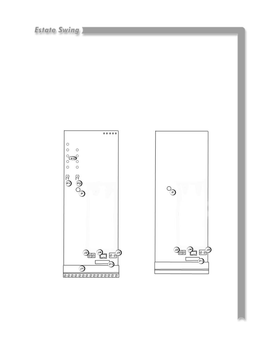
Control Board Layouts
Warnings:
•
Before attempting any job on the control board (connections, maintenance), turn
off electrical power and unplug the support battery.
•
Install a surge protector upstream of your opener, the opener is not power surge
proof nor will power surge damage be covered under warrantee.
•
Always separate power from control and safety cables (push-buttons, receivers,
photocells, etc.). To avoid any electrical noise, use separate sheaths or a shielded
cable (with earthed shield).
La
yo
u
t o
f M
a
s
te
r C
o
n
tr
o
l B
o
a
rd
La
yo
u
t o
f S
la
ve
C
o
n
tr
o
l B
o
a
rd
LED
Programming LEDs
P
Power ON and diagnostics LED
P1
“Function” programming push-button
P2
“Value” programming push-button
F1
Battery and motor fuse - F15A
J1
Accessories Terminal board
J2
Transformer Terminal board
J3
Motor connection terminal
J4
Battery connector
J5
Minidec connector/RP receiver
P
Power ON and diagnostic LED
F1
Battery and motor fuse - F15A
J2
Bus connection terminal board
J3
Motor connection terminal board
J4
Battery connector
2.1