The differential amplifier – Erica Synths EDU DIY Dual VCA Eurorack Module Kit User Manual
Page 23
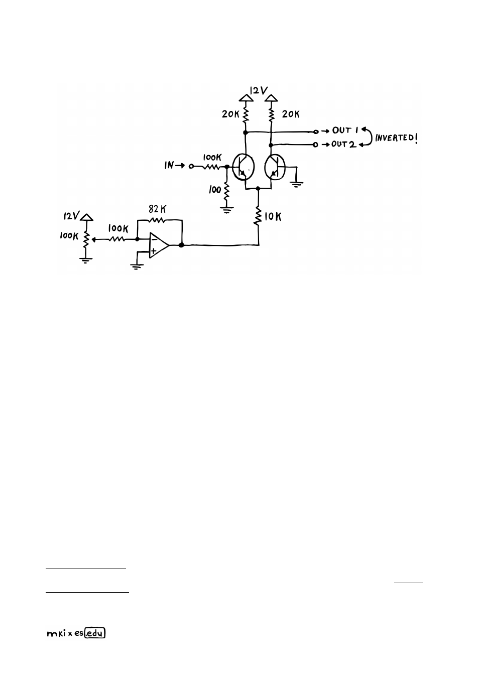
THE DIFFERENTIAL AMPLIFIER
The first change we’ll make probably looks very confusing at first glance: we are basically
copy-pasting our transistor and its collector resistor, while connecting both emitters to the
same, original emitter resistor. Also, we’re directly grounding the new transistor’s base.
What’s this supposed to achieve?
By doing this, we are turning our regular amplifier
into a di
ff
erential amplifier
. If that doesn’t mean much to you, no worries – I’ll walk you
through the circuit step by step.
Essentially, we are exploiting two interlinked mechanisms here. First, without any input
signal, there are two stable identical currents flowing through our transistors that
combine at their emitters and are then sunk by the op amp.
You could call this our total
bias current – which directly depends on the voltage at the op amp’s output
. The
more negative (below 0 V) that output goes, the stronger the total bias current will
become. This is because both transistors’ bases sit at (or around) 0 V while the VCA is
operating. And the bigger the voltage di
ff
erences between their bases and emitters get,
the more the transistors will open up.
Second, and just like before, we apply a heavily scaled-down version of our input signal
to the left transistor’s base. As the input signal oscillates, the bias current on the left hand
path will start to oscillate as well – simply because we’re further manipulating the voltage
between that transistor’s base and emitter. Now, as the bias current oscillates, it forces its
twin on the other side to oscillate as well – just in an inverted manner. This is because of
You can try this chapter’s circuit in a simulator. I’ve already set it up for you right her
–
you can change all values by double clicking on components.
Assuming that the transistors are closely matched – meaning that their base-voltage-to-
collector-current-curves should be close to identical.
23