5 process and instrumentation diagrams (p&ids) – Emerson SCROLL SZO44 User Manual
Page 14
8
2006SSD-75 R4 (10/10)
Dual-Compressor Module
Installation
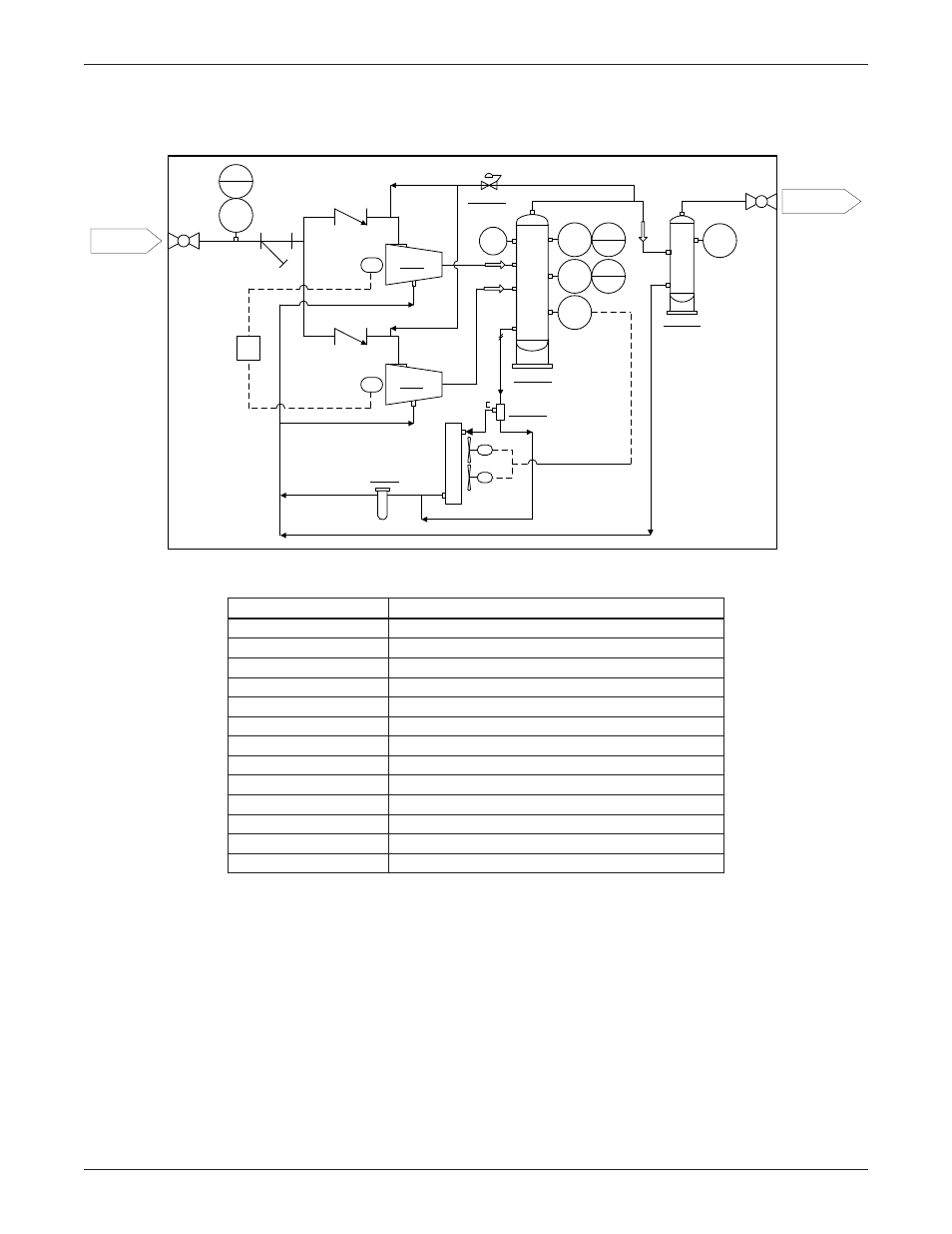
2.5 Process and Instrumentation Diagrams (P&IDs)
Figure 5 Compressor Module Gas and Oil Flow Diagram and Safety Shutdowns
PI
002
TE
002
TS
002
TSHH
002
PI
003
EX
-04
BPV-01
SEP-01
TCV-03
FL-05
PS
002
PSHH
002
PS
001
PSLL
001
480V
J.B.
SEP-02
Module Limits
Gas Suction
1-1/2" -NPT
Gas Discharge
1" -NPT
C-02
C-01
Code
Description
BPV-01
Gas bypass valve (optional)
C-01 / C-02
Compressor and motor
EX-04
Oil cooler, fan controlled by thermistor
FL-05
Oil filter
PI002
Pressure gauge on first-stage oil separator
PI003
Pressure gauge on second-stage oil separator
PS002 / PSHH002
High discharge gas pressure switch
PS001 / PSLL001
Inlet low pressure switch
SEP-01
First-stage oil separator, 6” O.D.
SEP-02
Second-stage oil separator/coalescing element
TCV-03
Thermal bypass valve, 3-way, set @ 200°F (93°C)
TE002
Fan speed thermistor
TS002 / TSHH002
High discharge gas temp switch