Avago Technologies MegaRAID SCSI 320-4X (531) User Manual
Page 2
2 of 4
lists the jumpers and connectors on the
MegaRAID 320-4X controller.
Table 1
Jumpers and Connectors
Step 4
Check the Memory Module.
Ensure that the memory is present and seated
firmly in the DIMM socket.
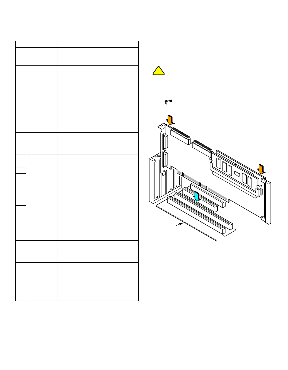
Step 5
Install the RAID Controller.
Install the MegaRAID 320-4X in a 3.3 V PCI or
PCI-X slot, as shown in
. Press down
gently, but firmly, on the top edge of the card to
seat the card properly in the slot. The bottom
edge of the controller card must be flush with the
slot. Attach the MegaRAID 320-4X to the
computer chassis with the bracket screw.
If your board has a memory module, never apply
pressure to the module when inserting the adapter.
Applying pressure could break the module.
Figure 2 Installing the MegaRAID 320-4X Board
Step 6
Connect SCSI Devices to the RAID Controller.
Connect the SCSI devices to the internal
high-density 68-pin SCSI connectors (J2 and J3)
and/or the external very high-density 68-pin SCSI
connectors (J5 and J21). For maximum data
throughput, use only Ultra320 SCSI devices. The
MegaRAID 320-4X supports up to 15 Ultra320
devices per channel (14 devices per channel on
storage systems with SCSI-access fault-tolerant
enclosures). The maximum SCSI bus cable
length is 12 m.
In addition, you can connect Ultra, Ultra2,
Ultra160, and Ultra320 SCSI devices (although
backward-compatible, SCSI uses the speed of the
Item Connector
Description
J1
SCSI Activity
LED
4-pin header.
Connector for SCSI activity LED to indicate
whether a SCSI channel is active. Optional.
J2
Internal SCSI
Channel 1
Connector
68-pin connector.
Internal, high-density SCSI bus connector.
Connection is optional.
J3
Internal SCSI
Channel 0
Connector
68-pin connector.
Internal, high-density SCSI bus connector.
Connection is optional.
J4
Double Data
Rate (DDR)
DIMM Socket
184-pin header.
Socket for mounting DDR SDRAM Dual
Inline Memory Module (DIMM). The
MegaRAID 320-4X supports 256 Mbytes of
100 MHz DDR error correcting code (ECC)
SDRAM.
J5
External SCSI
Channel 0, 1
Connectors
(Side-by-Side)
68-pin connector.
External, very-high-density SCSI bus
connector.
Connection is optional.
J6
Termination
Enable
for Channels 0–3
3-pin header.
No jumper: Software uses drive detection to
control SCSI termination (default).
Jumper on pins 1–2: Termination is
controlled through the 0xE007.0000 port
address.
Jumper on pins 2–3: Onboard SCSI
termination disabled.
J8
J10
J13
J7
Termination
Power Enable
for Channels 0–3
2-pin header.
Jumper installed enables TermPWR from the
SCSI bus to the appropriate SCSI channel.
J9
J11
J14
J17
Write Pending
Indicator (Dirty
Cache LED)
2-pin header.
Connector for enclosure LED to indicate
when data in the cache is to be written to the
device. Optional.
J21
External SCSI
Channel 2, 3
Connectors
(Side-by-Side)
68-pin connector.
External, very-high-density SCSI bus
connector.
Connection is optional.
J24
Onboard BIOS
Enable
2-pin header.
No jumper: Optional system BIOS is
enabled.
Jumpered: Optional system BIOS is
disabled.
Status of this jumper can be read through bit
0 at the 0x9F84.0000 local CPU address.
!
CAUTION
64-Bit Slots
(3.3 V)
Edge of
Mainboard
Bracket Screw
Press
Here
Press
Here