Avago Technologies MegaRAID SAS 8888ELP User Manual
Page 2
2 of 3
describes the jumpers and the connectors
on the SAS 8888ELP RAID Controller.
Table 1
Jumpers and Connectors
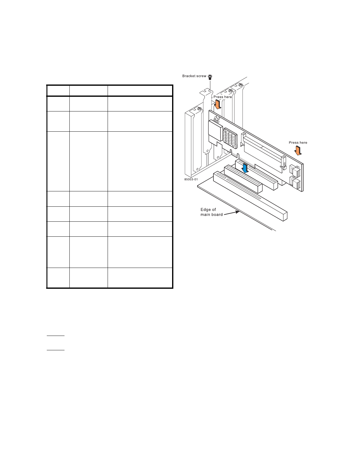
Step 4
Install the RAID Controller
Insert the RAID controller in a PCI Express slot
on the mainboard, as shown in
Figure 2
. Press
down gently but firmly to seat the card correctly
in the slot. Secure the RAID controller to the
computer chassis with the bracket screw.
Important: Refer to your mainboard guide for information
about the PCI Express slot.
Important: This is a PCI Express x8 card and can operate in
4x, 8x, and 16x slots.
Figure 2 Installing the MegaRAID SAS 8888ELP
RAID Controller
Step 5
Configure and Install the SAS Devices, SATA
II Devices, or Both in the Host Computer Case
Refer to the documentation for the devices for any
pre-installation configuration requirements.
Step 6
Connect the RAID Controller to the SAS
Devices, SATA II Devices, or Both
Use SAS cables to connect the SAS RAID
controller to SAS devices, SATA II devices, or
both. Refer to
to view connector
locations on the controller.
Refer to the MegaRAID 1078-based SAS RAID
Controllers User’s Guide on the MegaRAID
Universal Software Suite CD for detailed
information about the SAS cables.
Step 7
Turn on the Power to the Computer
Reinstall the computer cover, and reconnect the
power cords. Turn on the power to the computer.
Make sure that the power is turned on to the SAS
devices and the SATA II devices before or at the
same time that the power to the host computer is
turned on. If the power is turned on to the
computer before it is turned on to the devices, the
computer might not recognize the devices.
Jumper/
Connector Type
Description
J1
Serial header for
debug use
4-pin jumper.
Reserved for LSI use.
J2
IPMI-style SMBus
(System Manage-
ment)
/I
2
C header
3-pin (shielded) header.
Provides enclosure management
support.
J3
MiniDIMM bracket
Holds the cache memory module.
The SAS 8888ELP RAID controller
supports the following battery-
backed cache configuration:
- 256 MB, 72b arrangement (3)
64Mx16, Double Data Rate II @
667 MHz SDRAM intelligent trans-
portable battery-backed MiniDIMM
module
1.
Using unapproved memory
modules can void your limited
warranty.
J6
SAS Ports 0-3
The ports connect the cables from
the adapter to SAS or SATA II
physical drives, or a port multiplier.
J7
SAS Ports 4-7
The ports connect the cables from
the adapter to SAS or SATA II
physical drives, or a port multiplier.
J8
Serial Bootstrap
EEPROM
connector
2-pin connector.
Reserved for LSI use.
J9
Cache Write Pend-
ing LED
2-pin connector.
Connector for an LED mounted on
the system enclosure. The LED
indicates that the data in the cache
has yet to be written to the storage
devices.
J10
Battery Backup
connector (located
on the back side of
the controller)
20-pin connector.
Provides the interface to the bat-
tery pack.