Avago Technologies MegaRAID SAS 8704ELP User Manual
Page 2
2 of 3
describes the jumpers and the connectors
on the SAS 8704ELP RAID Controller and the
SAS 8708ELP RAID Controller.
Table 1
Jumpers and Connectors
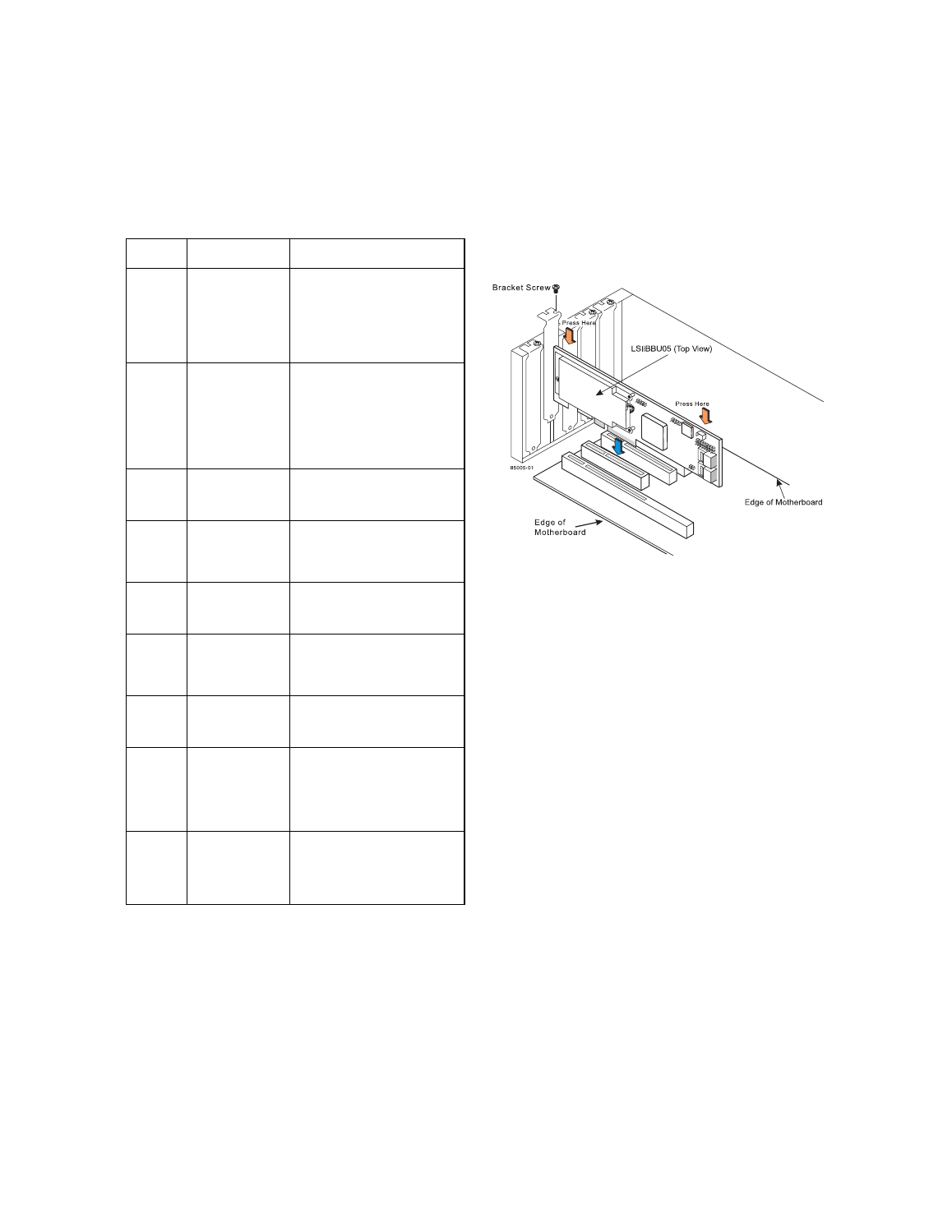
Step 4
Install the RAID Controller
Insert the RAID controller in a PCI Express slot
on the motherboard, as shown in
. Press
down gently, but firmly, to seat the card correctly
in the slot. Secure the RAID controller to the
computer chassis with the bracket screw.
Note:
Refer to the guide for your motherboard for
information about the PCI Express slot.
Note:
This is a PCI Express x4 card, and it can operate
in 4x, 8x, and 16x slots.
Figure 2 Installing the MegaRAID SAS 8708ELP
RAID Controller
Step 5
Configure and Install the SAS Devices, SATA
II Devices, or Both in the Host Computer Case
Refer to the documentation for the devices for any
preinstallation configuration requirements.
Step 6
Configure and Install the SAS Devices, SATA
II Devices, or Both in the Host Computer Case
Use SAS cables to connect the SAS RAID
controller to SAS devices, SATA II devices, or
both. See
to view the connector
locations on the RAID controller.
Refer to the MegaRAID 1078 SAS RAID
Controllers User’s Guide on the MegaRAID
Universal Software Suite CD for detailed
information about the SAS cables.
Step 7
Turn on the Power to the Computer
Reinstall the computer cover, and reconnect the
power cords. Turn on the power to the computer.
Make sure that the power is turned on to the SAS
devices and the SATA II devices before or at the
same time that the power to the host computer is
turned on. If the power is turned on to the
computer before it is turned on to the devices, the
computer might not recognize the devices.
The firmware takes several seconds to initialize.
During this time, the RAID controller scans the
ports.
Jumper/
Connector Type
Description
J1
Cache Write Pend-
ing LED
2-pin connector.
The connector for the enclosure
LED. It provides a signal that indi-
cates when the on-board cache
contains data and a write from the
cache to the hard drives is pend-
ing. Optional.
J2
On-board BIOS
Enable
2-pin shielded header.
The optional BIOS function is
enabled or disabled in software
depending on the status of this
jumper.
No jumper: BIOS is enabled
(default).
Jumper: BIOS is disabled.
J3
Universal Asyn-
chronous
Receiver/Transmit-
ter debugging
4-pin connector.
Reserved for LSI Logic use.
J5
Individual Fault
LED header for
eight SAS ports
16-pin connector.
Provides an LED interface individ-
ually to eight SAS ports. The LED
indicates errors on particular ports.
J6
IPMI-style SMBus
(System Manage-
ment)/I
2
C header
3-pin shielded header.
Provides enclosure management
support.
J7
Board-to-board
connector for bat-
tery backup unit
daughter card
20-pin connector.
Provides an interface to the daugh-
ter card that contains the battery
backup unit.
J8
x8 SAS Ports 0–3
The x4 SAS connectors connect
the cables from the RAID control-
ler to SAS or SATA II physical
drives or to a SAS expander.
J9
x8 SAS Ports 4–7
1.
The SAS
8704ELP RAID
Controller does
not contain this
connector.
The x4 SAS connectors connect
the cables from the RAID control-
ler to SAS or SATA II physical
drives or to a SAS expander.
J10
Straps Default Boot
Straps Controller
2-pin connector.
Loads the defaults in case the boot
strap controller (the serial ROM
that controls the memory and pro-
cessor speeds) becomes corrupt.