Avago Technologies MegaRAID SAS 9261-8i User Manual
Page 2
2 of 4
describes the jumpers and the connectors
on the RAID controller.
Table 1
Jumpers and Connectors
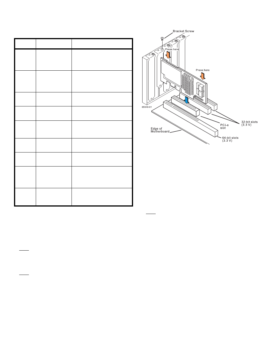
Step 4
Install the RAID Controller
Insert the controller into a PCI Express slot on the
motherboard, as shown in
gently, but firmly, to seat the card correctly in the
slot. Secure the
RAID controller
to the computer
chassis with the bracket screw.
Note:
This is a PCI Express x8 card and it can operate
in x8 or x16 slots. However, some PCIe slots
support only PCIe graphics cards; if a
RAID
controller
is installed, it will not function.
Note:
Refer to the guide for your motherboard for
information about the PCI Express slot.
Figure 2 Installing the MegaRAID SAS 9261-8i
RAID Controller
Step 5
Configure and Install the SAS Devices, SATA
II Devices, or Both in the Host Computer Case
Refer to the documentation for the devices for any
preinstallation configuration requirements.
Step 6
Connect the RAID Controller to the SAS
Devices, SATA II Devices, or Both in the Host
Computer Case
Use SAS cables to connect the
RAID controller
to
SAS devices, SATA II devices, or both. See
to view the connector locations.
Note:
Refer to the MegaRAID 6Gb/s SAS RAID
Controllers User’s Guide on the MegaRAID
Universal Software Suite CD for detailed
information about the SAS cables.
Step 7
Turn on the Power to the Computer
Reinstall the computer cover, and reconnect the
power cords. Turn on the power to the computer.
Make sure that the power is turned on to the SAS
devices and the SATA II devices before or at the
same time that the power to the host computer is
turned on. If the power is turned on to the
computer before it is turned on to the devices, the
computer might not recognize the devices.
The firmware takes several seconds to initialize.
During this time, the controller scans the ports.
Step 8
Run the WebBIOS Configuration Utility
Run the WebBIOS Configuration Utility to
configure the groups and the virtual drives. When
Jumper/
Connector Type
Description
J4L1
Remote Battery
Backup connector
(on the backside of
the controller)
20-pin connector
Connects the LSIiBBU07 intelli-
gent Battery Backup Unit remotely
to the RAID controller.
JT3B1
Battery Backup Unit
connector
20-pin connector
Connects the LSIiBBU07 intelli-
gent Battery Backup Unit directly
to the RAID controller.
JT5A1
x4 SAS Ports 0–3
Mini-SAS 4i
connector
Connects the cables from the
RAID controller to SAS drives or
SATA II drives, or a SAS expander.
JT5B1
x4 SAS Ports 4–7
Mini-SAS 4i
connector
Connects the cables from the
RAID controller to SAS drives or
SATA II drives, or a SAS expander.
JT5B2
Universal Asyn-
chronous Receiver/
Transmitter (UART)
debugging
4-pin connector
Reserved for LSI use.
JT5B3
Set Factory
Defaults connector
2-pin connector
Reserved for LSI use.
JT6B1
Test header
2-pin connector
Reserved for LSI use.
JT6B2
Global Drive Fault
LED header
2-pin connector
Connects to an LED that indicates
whether a drive is in a fault
condition.
JT6B3
SAS Activity LED
header
2-pin connector
Connects to an LED that indicates
drive activity.