Table 1 jumpers and connectors – Avago Technologies MegaRAID SAS 9260-4i User Manual
Page 2
2 of 4
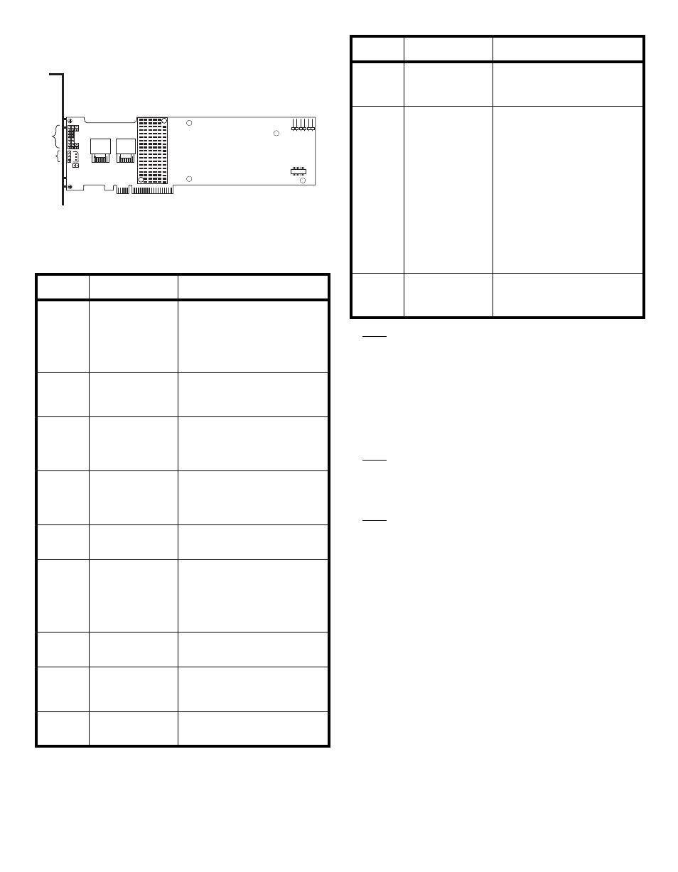
Figure 1 Layout of the MegaRAID SAS 9260-8i/
9260DE-8i RAID Controller
describes the jumpers and the connectors
on the SAS 9260 RAID controllers.
Table 1
Jumpers and Connectors
Note:
JT1, JT2, and JT4 are behind the LSIiBBU07
when it is installed, but they are still accessible.
Step 4
Install the RAID Controller
Insert the RAID controller in a PCI Express slot
on the motherboard, as shown in
. Press
down gently, but firmly, to seat the card correctly
in the slot. Secure the RAID controller to the
computer chassis with the bracket screw.
Note:
This is a PCI Express x8 card and it can operate
in x8 or x16 slots. However, some PCI-E slots
support only PCI-E graphics cards; if a RAID
controller is installed, it will not function.
Note:
Refer to the guide for your motherboard for
information about the PCI Express slot.
Jumper/
Connector Type
Description
JT1
Write-pending Indi-
cator (dirty cache)
LED connector
2-pin connector
Connects to an LED that indicates
when the data in the cache has yet
to be written to the storage
devices. Used when the write-back
feature is enabled.
JT2
SAS Activity LED
header
2-pin connector
Connects to an LED that indicates
drive activity.
JT3
Battery Backup
connector
20-pin connector
Connects the LSIiBBU07 intelli-
gent Battery Backup Unit directly
to the RAID controller.
JT4
Global Drive Fault
LED header
2-pin connector
Connects to an LED that indicates
whether a drive is in a fault
condition.
JT6
x4 SAS Ports 3–0
Mini SAS 4i
connector
Connects the cables from the con-
troller to SAS drives or SATA II
drives, or a SAS expander.
JT7
x4 SAS Ports 7–4
Mini SAS 4i
connector
Connects the cables from the con-
troller to SAS drives or SATA II
drives, or a SAS expander.
1.
The SAS 9260-4i RAID con-
troller does not have this con-
nector.
JT8
Modular RAID Key
header
2-pin connector
Reserved for LSI use.
JT9
Set Factory
Defaults connector
2-pin connector
Returns the board settings to the
defaults set in the factory.
JT10
LSI Test header
2-pin connector
Reserved for LSI use.
85039-04
Port
3-0
Port
7-4
JT10
JT3
JT4
JT2
JT12
JT1
JT8
JT13
JT11
JT9
JT7
JT6
JT11
IPMI-style SMBus
(System Manage-
ment)/I
2
C header
3-pin shielded header
Provides enclosure management
support.
JT12
Individual Drive
Fault LED header
for Eight Phys (0-7)
16-pin connector
Indicates drive faults. There is one
LED per port. When lit, each LED
indicates the corresponding drive
has failed or is in the Unconfig-
ured-Bad state. Refer to the
MegaRAID SAS Software User’s
Guide for more information.
The LEDs function in a direct-
attach configuration (there are no
SAS expanders). Direct attach is
defined as a maximum of one
drive connected directly to each
port.This header is used for RAID
controllers with internal SAS ports.
JT13
Universal Asyn-
chronous Receiver/
Transmitter (UART)
debugging
4-pin connector
Reserved for LSI use.
Jumper/
Connector Type
Description