Avago Technologies MegaRAID SAS 9240-4i User Manual
Page 2
2 of 4
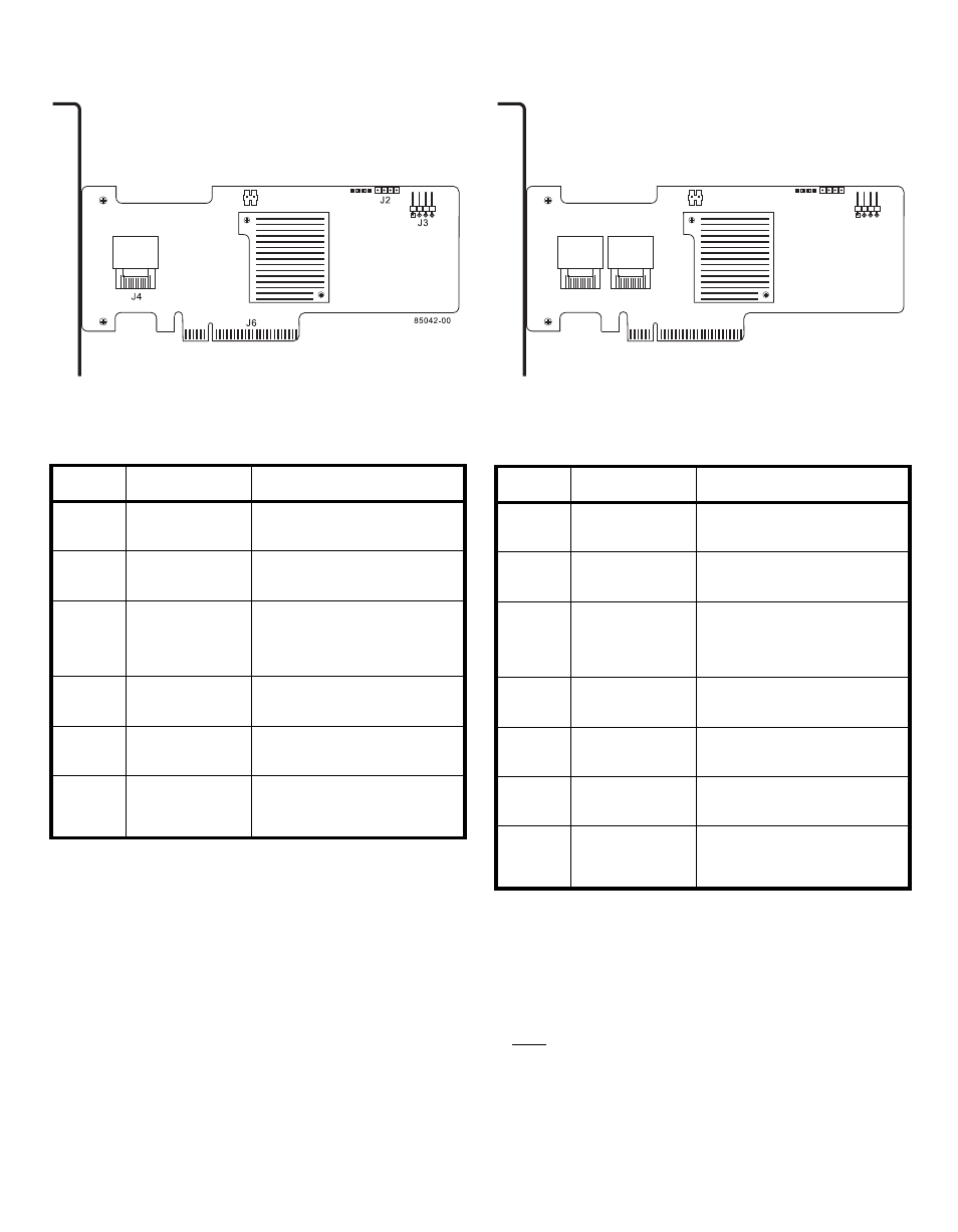
Figure 1 Layout of the MegaRAID SAS 9240-4i
RAID Controller
describes the jumpers and the connectors
on the SAS 9240-4i RAID controller.
Table 1
SAS 9240-4i Jumpers and Connectors
shows the location of the jumpers and the
connectors on the SAS 9240-8i RAID controller.
Figure 2 Layout of the MegaRAID SAS 9240-8i
RAID Controller
describes the jumpers and the connectors
on the SAS 9240-8i RAID controller.
Table 2
SAS 9240-8i Jumpers and Connectors
Step 4
Install the RAID Controller
Insert the RAID controller in a PCI Express slot
on the motherboard, as shown in
. Press
down gently, but firmly, to seat the card correctly
in the slot. Secure the RAID controller to the
computer chassis with the bracket screw.
Note:
Some PCI Express slots support only PCI
Express graphics cards; if a RAID controller is
installed, it will not function.
Jumper/
Connector Type
Description
J1
RISCwatch header
16-pin header
Reserved for LSI use.
J2
CPLD header
10-pin header
Reserved for LSI use.
J3
External LED drive
activity/fault header
4-pin connector
Connects to external, green or red
LEDs that indicate drive activity or
faults.
J4
x4 Mini-SAS (SFF-
8087) Ports 0–3
internal connector
Connects the cables from the
controller to SAS drives or SATA II
drives, or a SAS expander.
J6
PCI Express x8
board edge
connector
x8 interface that provides
connections on both the top and
the bottom of the board.
TP1
Universal Asyn-
chronous Receiver/
Transmitter (UART)
debugging
4-pin connector
Reserved for LSI use.
Jumper/
Connector Type
Description
J1
RISCwatch header
16-pin header
Reserved for LSI use.
J2
CPLD header
10-pin header
Reserved for LSI use.
J3
External LED drive
activity/fault header
4-pin connector
Connects to external, green or red
LEDs that indicate drive activity or
faults.
J4
x4 Mini-SAS (SFF-
8087) Ports 0–3
internal connector
Connects the cables from the
controller to SAS drives or SATA II
drives, or a SAS expander.
J5
x4 Mini-SAS (SFF-
8087) Ports 4–7
internal connector
Connects the cables from the
controller to SAS drives or SATA II
drives, or a SAS expander.
J6
PCI Express x8
board edge
connector
x8 interface that provides
connections on both the top and
the bottom of the board.
TP1
Universal Asyn-
chronous Receiver/
Transmitter (UART)
debugging
4-pin connector
Reserved for LSI use.
J4
J2
J6
85043-00
J5
J3