Powering up, Description of led functions, Powering up -3 – Enterasys Networks Network Ethernet Adapter User Manual
Page 25: Description of led functions -3, Bl-69551ent schematic block diagram -3, Data & power out data in
Powering Up
Single-Port Power Over Ethernet Adapter User’s Guide 2-3
Powering Up
Simply plug one end of the power cord or power supply into the
unit, and the other end into a grounded AC power source. Units
are typically connected to a power strip or other power outlet
that may be cycled on and off. An uninterruptible power supply
(UPS) may be used.
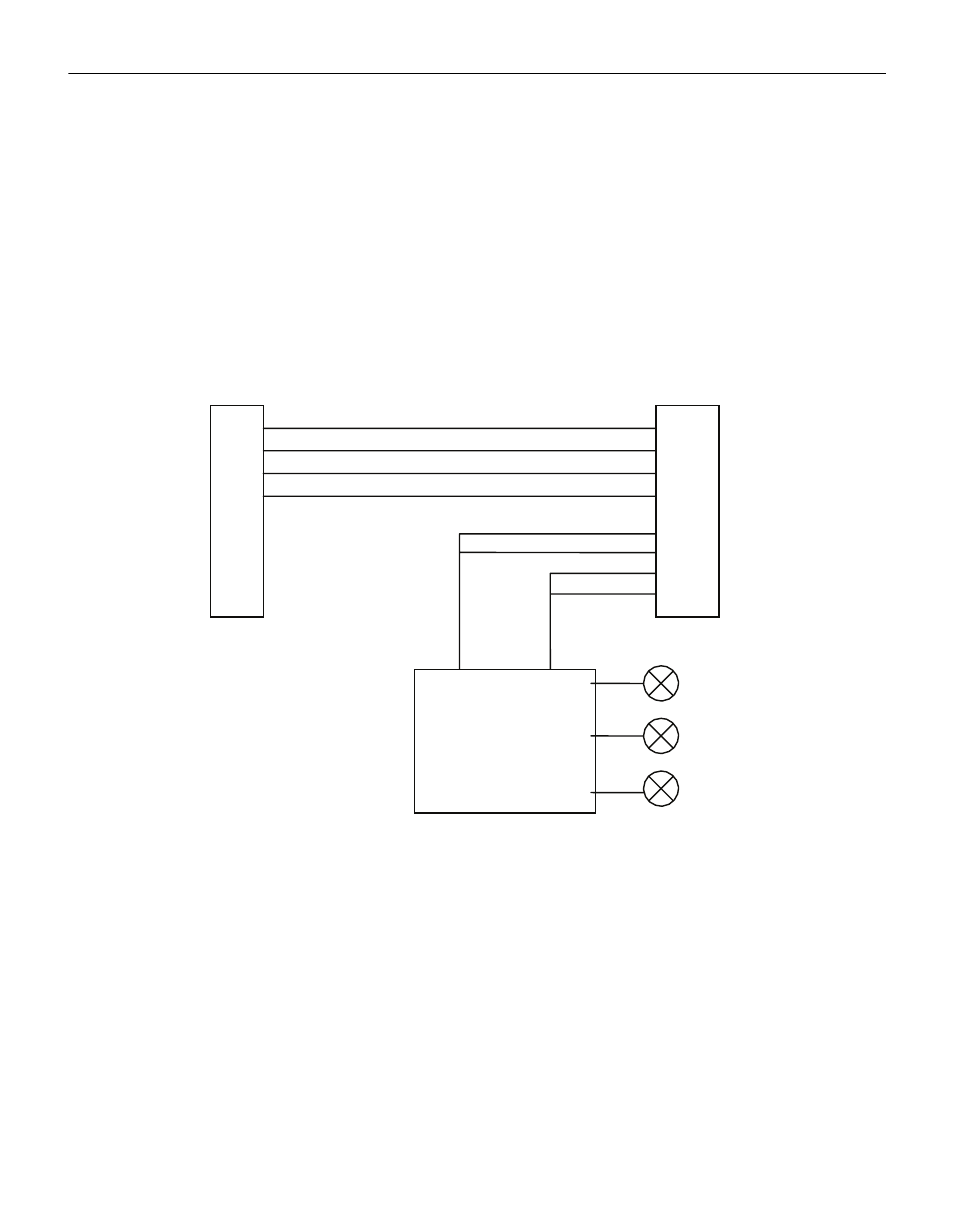
Figure 2-1 BL-69551ENT Schematic Block Diagram
Description of LED Functions
Power-up Sequence
Upon power‐up, all 3 LEDs will light for 2 seconds, as part of the
self‐test for the internal microprocessor software. After the end of
the 2 seconds, the “ON” LED will illuminate green, signifying
that the DC output voltage is available for powering a compliant
load (to the 802.3af PoE standards).
RJ45
+
-
RJ45
1
2
3
6
4
5
7
8
1
2
3
6
4
5
7
8
Data &
Power
Out
Data
In
ON (green)
FAULT (red)
CONNECT (green)
PoE
Power &
Control