Standing pilot wiring, Standing pilot wiring diagram – Empire Comfort Systems DV25IN33L User Manual
Page 20
23015-3-0707
Page 20
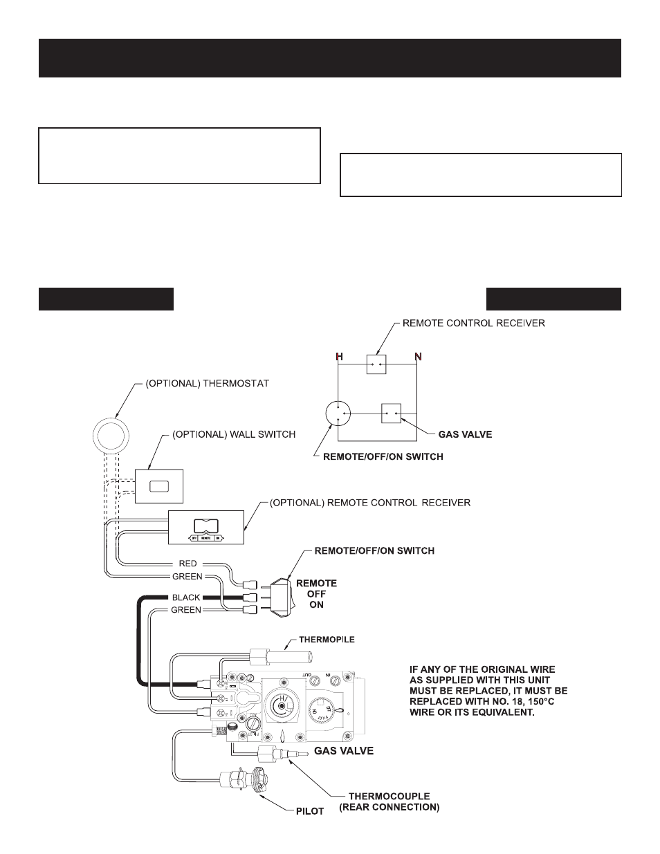
STANDING PILOT WIRING
STANDING PILOT WIRING DIAGRAM
For Standing Pilot Ignition Wiring
Appliance Requirements
WARNING: DO NOT CONNECT 110-120 VAC TO THE
GAS CONTROL VALVE OR THE APPLIANCE WILL
MALFUNCTION AND THE VALVE WILL BE DE-
STROYED.
Optional Wall Switch
Position the wall switch in the desired position on a wall. Run a
maximum of 25 feet (7.8m) or less length of 18 A.W.G. minimum
wire and connect it to the fireplace valve pigtails.
WARNING: DO NOT CONNECT THE 110-120 VAC
TO THE WALL SWITCH OR THE CONTROL VALVE
WILL BE DESTROYED.
CAUTION: LABEL ALL WIRES PRIOR TO DISCONNEC-
TION WHEN SERVICING CONTROL. WIRING ERRORS
CAN CAUSE IMPROPER AND DANGEROUS OPERATION.
VERIFY PROPER OPERATION AFTER SERVICING.