Fig. 3 – Whelen HDACF User Manual
Page 2
Page 2
SHIELD
CLIP
WHITE
BLACK
RED
SHIELD
BLACK
WHITE
RED
OBSERVE COLOR AND PIN NUMBERS. CABLES CONNECTING REMOTE
POWER SUPPLY TYPE STROBE LIGHTS MUST BE CONNECTED CORRECTLY!
INTERMIXING STROBE LIGHT SYSTEM EQUIPMENT
Whelen Engineering and Aero-flash wiring
between light assemblies and remote
power supplies are identical as pictured
below.
Grimes and SDI (Hoskins) wiring between
light assemblies and remote power sup-
plies are identical as pictured below.
Both Grimes and SDI sometimes use MS
(Cannon Type) Connectors:
A
B
C
= RED (Anode), = WHITE (Trigger),
= BLACK (Ground)
PIN 1 = RED (ANODE)
PIN 2 = BLACK (CATHODE)
PIN 3 = WHITE (TRIGGER)
SHIELD = RFI DRAIN TO GROUND
POWER
1
X
3 POS. PIN HSG
3 CONDUCTOR SHIELDED CABLE
SHIELD WIRE
CUT AND TAPE SHIELD WIRE
AT STROBE TUBE END
GROUND SHIELD WIRE
AT POWER SUPPLY END
3 POS. SOCKET HSG
1
SUPPLY
STROBE
TUBE
END
2
2
END
3
3
Interconnecting Cable
1.
The Whelen interconnecting cable shall be secured in place with
approved aviation techniques.
2.
The cable shall not parallel ADF, Gyro or Flux Gate compass leads
closer than 12 inches.
3.
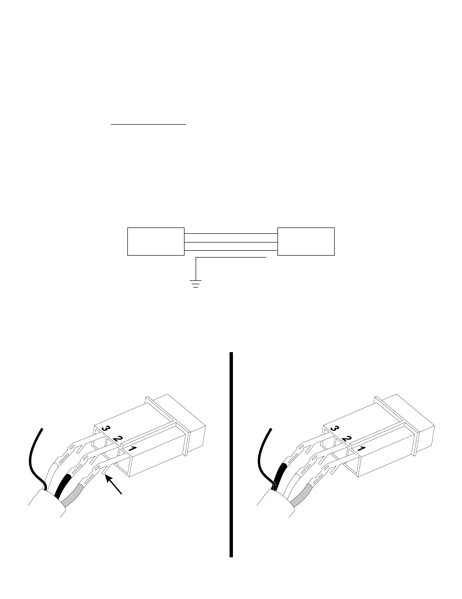
CABLE COLORING CODING (see Figure 3):
PIN 1 - RED (Anode)
PIN 2 - BLACK (Cathode, flash tube ground)
PIN 3 - WHITE (Trigger)
SHIELD - Ground at power supply end only
CAUTION: When pins 1 & 2 or pins 2 & 3 are reversed, the
system will appear to operate normally, however this condi-
tion will cause premature flash tube failure.
Fig. 3
IMPORTANT NOTE:
Your new strobe power supply has an additional circuit
built-in to prevent self-ionization (steady glowing) of the
strobe tubes. In some cases, when replacing older power
supplies, the bare shield wire in the existing harness is
pinned together at each end with the black wire. The
following modification must be made to ensure proper
operation.
1.
At the strobe tube end of the cable, cut the shield wire and tape it off
(DO NOT CUT THE BLACK WIRE).
2.
At the power supply end of the cable, cut the shield wire and connect
it to a good ground (DO NOT CUT THE BLACK WIRE).
3.
This must be done for each strobe light connection (see Fig. 3).