How to hang your ceiling fan, Warning – Emerson CF2455ORB00 User Manual
Page 7
7
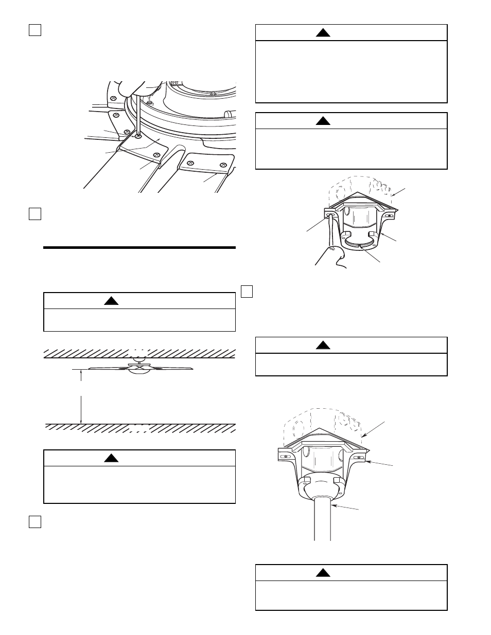
The outlet box and joist must be securely mounted
and capable of supporting at least 50 lbs. Use only a
U.L. outlet box listed as “Acceptable for Fan
Support”.
WARNING
!
Hanger bracket must seat firmly against outlet box. If
the outlet box is recessed, remove wall board until
bracket contacts box. If bracket and/or outlet box are
not securely attached, the fan could wobble or fall.
WARNING
!
TWO SCREWS
SUPPLIED WITH
OUTLET BOX
HANGER
BRACKET
TAB
OUTLET
BOX
Figure 12
How to Hang
Your Ceiling Fan
NOTE: CEILING COVER, SUPPLY WIRES AND FAN WIRES OMITTED FOR CLARITY.
OUTLET
BOX
HANGER
BRACKET
HANGER BALL/
DOWNROD ASSEMBLY
Figure 13
To avoid possible fire or shock, do not pinch wires
between the hanger ball/downrod assembly and the
hanger bracket.
WARNING
!
20. Position one fan blade on the flange assembly
and secure by installing the left and right blade
holder caps using two 10-32 x 3/8” pan head
screws (supplied) for each holder cap (Figure 10).
Install the remaining four fan blades using the
same procedure.
LEFT BLADE
HOLDER CAP
FLANGE
ASSEMBLY
10-32 X 3/8"
PAN HEAD SCREW
(2 PER HOLDER CAP)
RIGHT BLADE
HOLDER CAP
Figure 10
21. You have now completed the initial assembly of your
new ceiling fan. You can now proceed with hanging
and wiring your fan.
CEILING
FLOOR
AT LEAST
7'
Figure 11
The fan must be hung with at least 7' of clearance
from floor to blades (Figure 11).
WARNING
!
1. Securely attach the hanger bracket to the outlet box
using the two screws supplied with the outlet box.
(Figure 12.)
To reduce the risk of fire, electric shock, or personal
injury, mount fan to outlet box marked “Acceptable
for Fan Support”, and use screws supplied with
outlet box. Most outlet boxes commonly used for
support of light fixtures are not acceptable for fan
support and may need to be replaced. Consult a
qualified electrician if in doubt.
WARNING
!
2. Carefully lift the fan and seat the hanger
ball/downrod assembly on the hanger bracket that
was just attached to the outlet box (Figure 13). Be
sure the groove in the ball is lined up with tab on
the hanger bracket (Figure 12).
Failure to seat tab in groove could cause damage to
electrical wires and possible shock or fire hazard.
WARNING
!