Primary height control valve, Primary height control valve adjustment, Maintenance – SAF-HOLLAND XL-AR363-02 EDL/ARF Feature User Manual
Page 13
XL-AR363-02 Rev. D
13
MAINTENANCE
continued
Operating
Height
Ride
Height
Support at King Pin
Axle
CL
Ride
Height
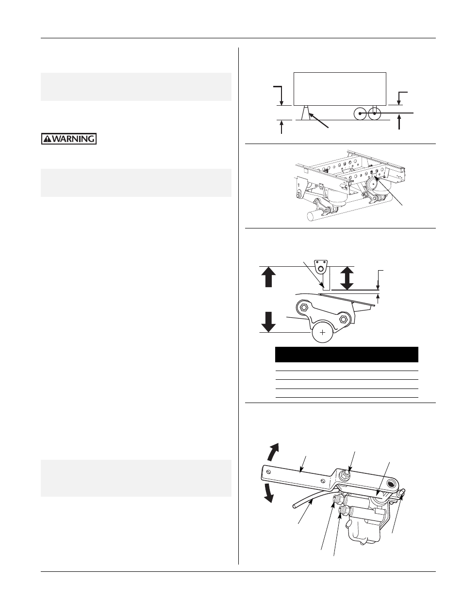
45˚ Intake
(Up)
Control
Arm
1/4˝ Adjusting
Lock Nut
Adjusting
Block
Locating Pin
(Remove After
Adjustments)
45˚ Exhaust
(down)
FIGURE 27
Trailer Supported at Fifth Wheel Height
FIGURE 29
Obtaining Proper Ride Height
FIGURE 30
Primary Height Control Valve
5/8˝ MIN.
(16mm)
Clearance must
be maintained
between
bottom of
flipper plates
and beam pads.
Exhaust (Top Port)
For EDL/ARF applications,
line is run to Sensor Valve
top port
To Air Springs
(Always Center Port)
Supply (Always Bottom Port)
“A”
Flipper Plate
RIDE
“A”
HEIGHT
FLIPPER PLATE HEIGHT
16.0˝ (406mm)
6.5˝ (165mm)
16.5˝ (419mm)
7.0˝ (178mm)
17.0˝ (432mm)
7.5˝ (191mm)
18.0˝ (457mm)
8.5˝ (216mm)
Serial Number Tag
Located on Rear
Crossmember
FIGURE 28
Serial Tag
Primary Height Control Valve Adjustment
Height Control Valve Adjustment Procedures
IMPORTANT:
This adjustment procedure is for ONE Height
Control Valve system with an External Dock
Lock Device
1. Prior to adjustment, the vehicle must be in an unladen condition on
a level floor and supported on a king pin stand or coupled to a
tractor (FIGURE 27).
Failure to properly support suspension
during maintenance may allow
suspension to fall which, if not avoided, could result in
death or serious injury.
IMPORTANT:
DO NOT
use flipper plate height plus 5/8˝
(16mm) clearance spacing to determine ride
height setting.
2. Verify ride height by checking serial number tag located on the frame
bracket or crossmember (FIGURE 28).
Example:
NS400/450-4816, last two digits
represent 16˝ (406mm) ride height.
3. Confirm proper EDL flipper plate rod assembly by comparing
predetermined ride height to corresponding EDL flipper plate
height (FIGURE 29, see chart).
4. Disconnect primary height control valve linkage to lower mounting
bracket, and move control arm up 45˚ and hold for 10-15 seconds to
raise vehicle. Return control arm to center (neutral) position.
5. Move control arm down 45˚ and hold until system air exhausts
completely, lowering flipper plates. Return control arm to center
(neutral) position, and check for proper ride height (determined in
step 2—FIGURE 29).
6. Insert the locating pin into the adjusting block and bracket on the
height control valve (FIGURE 30). Loosen the 1/4˝ adjusting lock
nut located on the adjusting block (FIGURE 30), allowing the
control arm to move up and down approximately 1˝ (25mm).
Replace lower link bolt back into lower link and mounting bracket.
DO NOT
fasten.
7. Tighten adjusting lock nut at the adjusting block to 30-40 in. lbs.
(3.75-5 Nm), and remove locating pin inserted in Step 6.
8. Remove lower link bolt, and raise control arm 45˚ and hold for
10-15 seconds (FIGURE 30). This will raise the vehicle. Bring the
control arm back to center (neutral) position.
9. Reconnect linkage to lower mounting bracket and fasten connection.
NOTE:
If the suspension returns to a dimension less than
design ride height, loosen the 1/4˝ adjusting nut and
adjust (up) so suspension will always return to its correct
ride height. NEVER LESS THAN DESIGN HEIGHT.