Auto reset (sensor) valve pe, Auto reset (sensor) valve performance check, Maintenance – SAF-HOLLAND XL-AR363-02 EDL/ARF Feature User Manual
Page 10: Auto reset (sensor) valve
XL-AR363-02 Rev. D
10
MAINTENANCE
Auto Reset (Sensor) Valve Performance Check
To check the Sensor Valve for proper adjustment and
operation, perform the following procedures.
Failure to chock tires prior to beginning
maintenance could allow vehicle rollaway
which, if not avoided, could result in death or
serious injury.
NOTE:
Apply air system pressure in excess of 85 psig (5.9 bars)
before doing performance check.
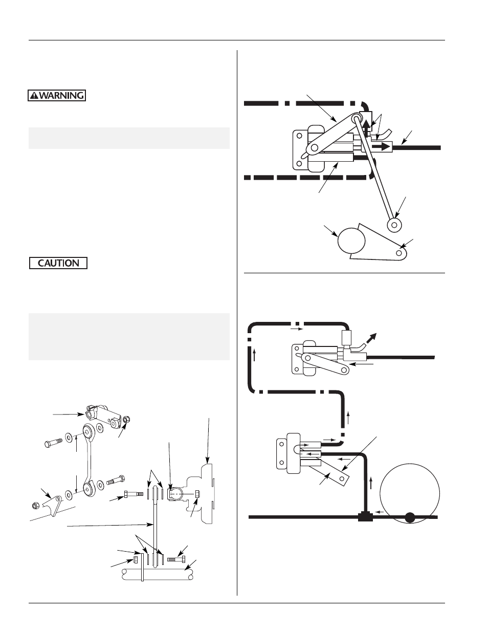
1. Disconnect the auto reset (sensor) valve lower linkage connection to
the EDL rod assembly. Rotate valve arm up approximately 20˚ and
hold (FIGURE 19). Air should flow through one-way check valve
ports to air springs (FIG. 19).
2. Move valve arm down 20˚ (FIGURE 20) and hold. Disconnect the
primary height control valve upper linkage connection. Rotate
primary height control valve arm down approximately 45˚ and hold
for 5-10 seconds. Air should flow (exhaust) out top port of auto
reset (sensor) valve (FIGURE 20).
3. Reconnect sensor valve and primary height control valve linkages.
In the event replacement of the
sensor valve is necessary, replace with
sensor valve ONLY. Use of primary height control valve
(1/4˝ [6.35mm] or 3/8˝ [9.53mm] air lines) in place of
sensor valve will result in malfunction of the auto reset
feature and possible damage to suspension and/or trailer.
NOTE:
To prevent side loading on sensor valve linkage
connection—fastening hardware MUST be assembled as
shown in (FIGURE 21) for proper function. If not
assembled as shown, disconnect linkage assembly and
refasten as shown.
Auto
Reset
(Sensor)
Valve
Air should be
flowing out of
both check
valve ports
Air should exhaust
out top port of
sensor valve
Sensor Valve
Arm down 20˚
below horizontal
Disconnect upper
linkage connection
Auto
Reset
(Sensor)
Valve
Primary
Height
Control
Valve
Air
Spring
Hold Primary HCV Arm down
45˚ below horizontal for
10-15 seconds
FIGURE 19
Auto Reset (Sensor) Valve (EDL Engaged) Air Flow
Check
FIGURE 20
Auto Reset (Sensor) Valve Air Flow Check
Disconnect
Lower
Linkage
EDL Rod Assembly
Bottom Port
Valve Arm in up position
(above horizontal)
To Air
Springs
FIGURE 21
Auto Reset Sensor Valve Linkage Assembly
4
3
/
4
˝± 1/8˝
(120.65±
3.18mm)
Must use Nylok
1/4˝- 20 nut (2
places)
Shoulder
Bolt
EDL Rod
Assembly
Flat Washers
Nylok
Nut
Shoulder
Bolt
Sensor
Valve
Nylok Nut
Link - Must
be vertical
to prevent
side loading
Sensor
Valve Arm
Nut Slot
Flat
Washers
Tab
Sensor
Valve
Arm
Tab
Tab