Hydraulic component installation – SAF-HOLLAND XL-FW488 FW2800 and FW2900 Series Hydraulic Elevating Fifth Wheel User Manual
Page 7
XL-FW488 Rev A
7
POWER TAKE OFF (PTO) AND
HYDRAULIC PUMP INSTALLATION
continued
Hydraulic Component Installation
continued
NOTE: Hose and fittings for these connections are to be supplied by the
customer/installer.
4.
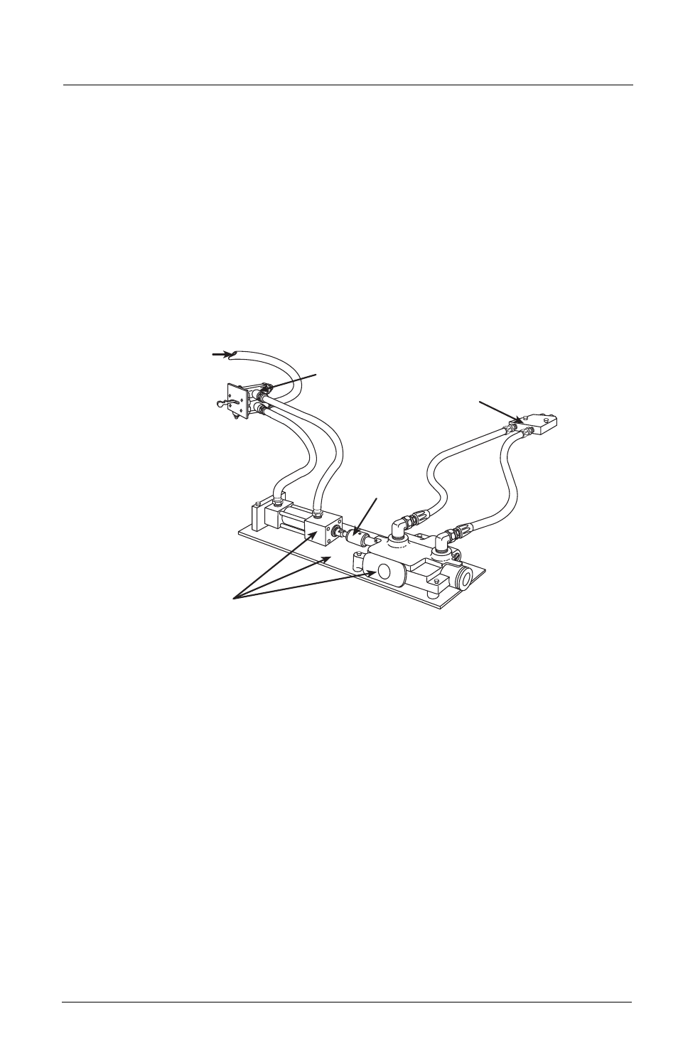
Connect the air lines from the lift control valve to the control valve/air
cylinder.
5.
Connect the hydraulic hoses from the hydraulic valve to the hydraulic
manifold.
6.
Operate the air lift control valve in both the up and down position, and
inspect the hydraulic control valve. In either position, the hydraulic
control valve must be fully actuated. If not, adjust the coupling until full
stroke is achieved (see Figure 8.)
3.
Install all hydraulic hoses and fittings (as shown in the piping diagrams on pages
9 and 10) for the model selected. Use care to assure that all hoses and fittings are
clear and free from foreign material and that all joints are properly sealed.
4.
Fill and bleed the hydraulic system.
A.
Have, on hand, sufficient hydraulic oil for the model selected. The
approximate system volumes are given below:
MODEL:
SYSTEM VOLUME
FW2800-X
7
1
/
2
gallons
FW2800-5X
12 gallons
FW2900-X
6 gallons
FW2900-5X
9
1
/
2
gallons
NOTE: These volumes are approximate and will vary somewhat from
installation to installation. They are designed to provide
approximately 2-1/2 gallons reserve in the oil tank when the system is
filled and bled.
LIFT CONTROL VALVE
FROM
TRACTOR
AIR SUPPLY
HYDRAULIC MANIFOLD
ADJUSTABLE
COUPLING
CONTROL VALVE/AIR CYLINDER ASSEMBLY
Figure 8