Installation instructions – SAF-HOLLAND XL-FW488 FW2800 and FW2900 Series Hydraulic Elevating Fifth Wheel User Manual
Page 5
9.
Remove the rear pivot shaft (see corresponding fifth wheel’s parts list — pages 11
through 12 — in combination with Chart 2 — to find the rear pivot shaft):
Chart 2
Rear Pivot Shaft Identification
FIFTH WHEEL
REAR PIVOT SHAFT
REAR PIVOT SHAFT
PART NUMBER
PART NUMBER
DETAIL NUMBER
FW2800-X
XA-2895
Detail #7
FW2900-X
XA-2895
Detail #7
FW2800-5X
XA-2895
Detail #37
FW2900-5X
XA-2895
Detail #37
10.
Using a lifting device, pick up the rear support assembly (see corresponding fifth
wheel parts list in combination with Chart 3 to find the rear support assembly). For
safety, block out the assembly after it is lifted.
Chart 3
Rear Support Assembly Identification
REAR SUPPORT
REAR SUPPORT
FIFTH WHEEL
ASSEMBLY
ASSEMBLY
PART NUMBER
PART NUMBER
DETAIL NUMBER
FW2800-X
XA-2808-B
Detail #2
FW2900-X
XA-2908-B
Detail #2
FW2800-5X
XA-2808-B
Detail #32
FW2900-5X
XA-2908-B
Detail #32
11.
Use air pressure to extend the cylinder rod(s) approximately 12˝
. Be sure to cover
the cylinder rod(s) to protect from weld splatter.
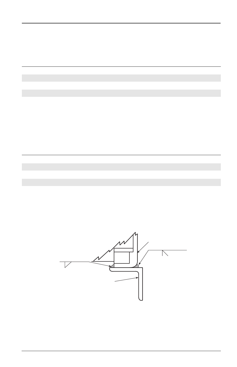
12.
Weld the fifth wheel frame to the mounting angles per
Figure 7. Make 5/16˝ fillet
skip welds inside the frame, and 3/8˝ groove skip welds on the outside. Make the
skip welds 3˝ long on approximately 8-1/2˝ centers (i.e. weld 3˝ bead, skip 5-1/2˝).
Make inside skip welds opposite to the outside welds.
13.
Reassemble the rear pivot shaft removed in Step 9.
XL-FW488 Rev A
5
INSTALLATION INSTRUCTIONS
continued
5/16˝
3- 8
1
/
2
˝
3/8˝
3- 8
1
/
2
˝
FIFTH WHEEL
MOUNTING FRAME
MOUNTING ANGLE
Figure 7