Thermo Pride Air Handler MA User Manual
Page 25
9
External Relay Outputs
The control includes two outputs to drive external relays having 24 VAC
coils. The outputs have a maximum rating of 1.0 Amp pilot duty at 24
VAC.
HUM OUT
The HUM OUT output can be used to drive an external relay or solenoid
(24 VAC coil) to control a humidifier. The output is energized when the
HUM input is energized, the HUM STAT is in the YES position, and the
control has a thermostat call for heating (heat pump or electric heat).
EAC
The EAC output can be used to drive an external relay (24 VAC coil) to
control an electronic air cleaner. The output is energized whenever the
blower relay on the control is energized.
Heat Output and Limit Connections
The control is connected to the heater relays and limit switch using the
6-pin connector. The relay outputs and the limit switch signal are 24
VDC.
The control energizes the heat relays and senses the limit switch input
as shown in Table 4 when the HEAT ENABLE jumper is in the HEAT
position.
The control energizes the first stage of electric heat immediately, the
second stage 10 seconds after the call for second stage heat, and the
third stage 20 seconds after the call for third stage heat.
Depending on the heat kit installed in the air handler, the control pro-
vides the flexibility to configure the amount of heat delivered with the
first stage heating call. As an example, when the control’s W1 input is
connected to the room thermostat’s first stage heat signal, a call for first
stage heat will energize one heating element (HT1). If the control’s W2
input is connected to the room thermostat’s first stage heat signal, a call
for first stage heat will energize two heating elements (HT1 and HT2).
With either configuration, the control will energize three heating ele-
ments (HT1, HT2, and HT3) when it receives a first and second stage
heat input from the thermostat.
Limit Switch and Lockout Operation
Limit Switch Operation
If the HEAT ENABLE jumper is in the HEAT position and the limit switch
opens (fault code 1), the control will immediately de-energize all electric
heat relay outputs and energize the blower (if it wasn’t already ener-
gized). When the limit switch closes, the control will re-energize electric
heat according to the thermostat inputs using normal timings.
Fan On Lock Condition
If the limit switch opens multiple times during a single call for electric
heat (fault code 3) or if the limit switch opens for a long duration (fault
code 4), the control will energize the blower until power is removed from
the control. The control will cycle the heat outputs on and off as the limit
re-closes and opens. The constant fan operation will signal the home-
owner that a problem has occurred and a service call is required.
Soft Lockout
If the limit switch opens for a second long duration period during a sin-
gle call for heat (fault code 5), the control will keep the blower locked on
and lock out the heat outputs for one hour. The control will only reset
this one hour lockout when the power is removed from the control. After
the one hour period has passed, the control will re-energize electric
heat according to the thermostat inputs using normal timings. The
blower will remain locked on from the first long duration limit opening.
Hard Lockout
The control has a hard lockout condition during which the control will
keep all heat outputs de-energized until power is removed from the con-
trol. The control de-energizes the blower five minutes after entering the
hard lockout condition.
If the limit switch closes and re-opens during the one hour soft lockout
period, the control will enter a hard lockout condition and continue to
indicate a fault code 5.
If the limit switch opens twice when no call for electric heat is present
(fault code 2), the control will enter a hard lockout condition.
If the limit switch opens multiple times soon after a soft lockout reset
(fault code 6), the control will enter a hard lockout condition.
Wiring Related Faults
If the control receives a simultaneous call for heating and cooling (fault
code 7), the control will perform both heating and cooling operations.
SECTION VII: LINE POWER CONNECTIONS
Power may be brought into the unit through the supply air end of the
unit (top when unit is vertical) or the left side panel. Use the hole appro-
priate to the unit’s orientation in each installation to bring conduit from
the disconnect. The power lead conduit should be terminated at the
electrical control box. Refer to Tables 10, 11, 13 or 14 to determine
proper wire sizing. Also see Figure 3. To minimize air leakage, seal the
wiring entry point at the outside of the unit.
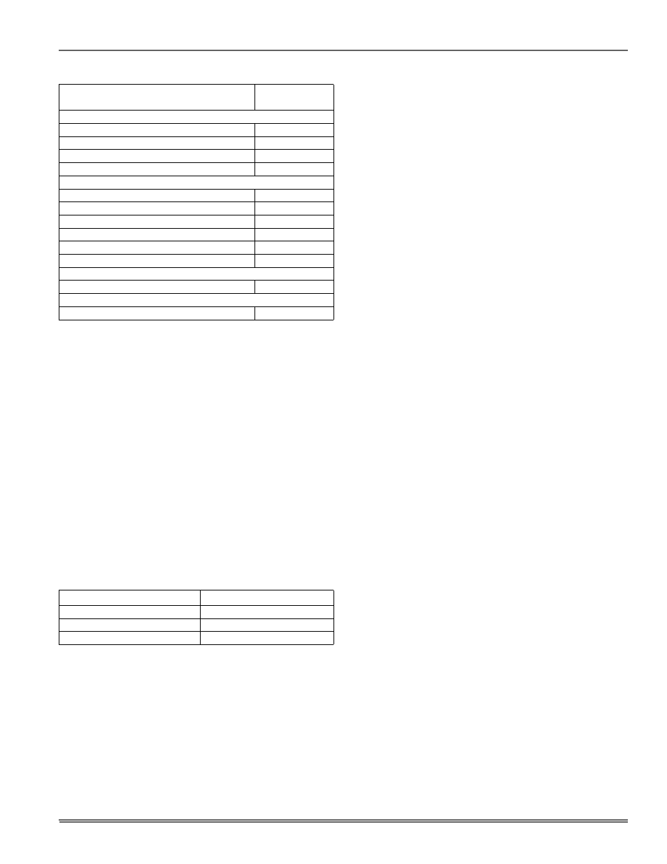
TABLE 3: Fault Codes
Fault or Status Condition
LED1 (RED)
Flash Code
Status
No power to control
OFF
Normal operation
2s ON / 2s OFF
Control in test mode
Rapid Flash
Control failure
ON
Limit Faults
Limit switch currently open (not in lockout)
1
Multiple limit openings with no call for heat
2
Multiple limit openings during one call for heat
3
Single long duration limit opening
4
Multiple long duration limit openings
5
Fan failure
6
Wiring Related Faults
Simultaneous call for heating and cooling
7
Internal Control Faults
Control recovered from internal event
9
TABLE 4: Heat Relays
Input
Heat Relay Output
W1
HT1
W2
HT1 and HT2
W1 and W2
HT1 and HT2 and HT3