5 checking functional members – Subaru Robin RGX3600 User Manual
Page 24
– 21 –
4-5 CHECKING FUNCTIONAL MEMBERS
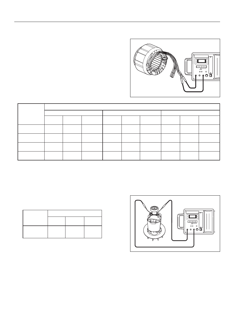
(1) STATOR
Disengage connectors on the wires from stator and
check the resistance between the wires using a circuit
tester referring to the table below.
NOTE : If the circuit tester is not sufficiently accurate, it may not show the values given and may give erroneous readings.
Erroneous readings will also occur when there is a wide variation of resistance among coil windings or
when measurement is performed at ambient temperature different from 20 C (68 F).
(2) ROTOR
Measure resistance between the field coil.
NOTE1 : When measuring the field coil resistance, be sure
to disconnect the soldering connection and take
out diode rectifier and surge absorber.
NOTE2 : When measuring, tolerance should be considered
because of the tester inaccuracy, winding number
variation, ambient temperature etc.
(Wire color)
(Black - Blue)
(Red - White)
(Yellow - Yellow)
(Brown - Brown)
Coils
RGX2900
RGX4800
RGX3600
Coil resistance (
Ω)
50Hz-240V 60Hz-120/240V
50Hz-220V
50Hz-230V
60Hz-120/240V
50Hz-220V
50Hz-230V
60Hz-120/240V
50Hz-220V
50Hz-230V
50Hz-240V
50Hz-240V
AC coil 1
AC coil 2
DC coil
0.8
0.6
0.4
0.8
0.6
0.4
2.2
1.3
0.9
0.3
0.2
0.2
0.9
0.9
2.2
0.3
0.6
0.6
1.7
0.2
0.7
0.7
1.3
0.2
0.4
0.4
1.0
0.2
0.4
0.4
0.9
0.2
0.3
0.3
0.6
0.1
Condenser coil
RGX2900
RGX4800
RGX3600
1.8
1.6
1.6
Coil resistance (
Ω)
Field coil