Controls and installation, cont’d, Setting internal jumpers, Caution – Extron Electronics RGB 160 User Manual
Page 11
RGB 160xi and RGB 164xi • Controls and Installation
Controls and Installation, cont’d
2-12
Setting internal jumpers
The jumpers inside the interfaces are set at the factory for
optimal use by most systems. However, you can change a
jumper setting to meet the needs of a particular system.
Changes to internal jumper settings must be
performed by authorized service personnel only.
The user-configurable, internal jumpers control the following
functions:
• Horizontal and vertical sync polarity
• Vertical sync pulse width
Follow these steps to change the jumper settings. The RGB 164xi
is shown for illustration, but the steps apply to both interfaces.
1
.
Remove power from the interface by disconnecting the AC
power cord from the unit.
2
.
Open the cover of the interface (the top half of the
enclosure) as follows:
a
.
Remove the screws from the top cover of the
enclosure (figure 2-14).
b
.
Remove the three screws that are in the Output 1
BNC group.
c
.
Lift the cover straight up.
CAUTION
Do not touch any switches or electronic components
inside the interface. Doing so could damage the
interface.
Remove (5)
screws.
Slide cover back slightly,
lift straight up.
Figure 2-14 — Opening the interface cover
RGB 160xi and 164xi • Controls and Installation
3
.
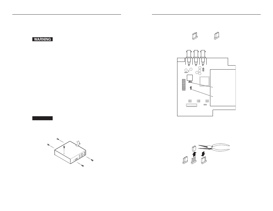
Note the positions of jumpers J20 and J40 before changing
jumper settings. Figure 2-15 shows the locations of the J20
and J40 jumpers and the two possible setting combinations
for 3-pin jumpers.
J19
1
J40
1
J20
1
Front
Rear
Power Supply
J20: Sync polarity
jumper
J40: Vertical sync
width jumper
Figure 2-15 — Circuit board jumper locations
4
.
Configure the jumpers as defined on the next page. To
configure the jumpers, use pliers to pull the jumper shunt
off the pins, then place the jumper on the appropriate pins
(figure 2-16).
Figure 2-16 — Changing jumper settings
2-13
Pin 1 to 2
Pin 2 to 3