Installation guidelines, Mounting – Rosen Aviation 0603 Series : Rosenview MX User Manual
Page 13
Rosen Aviation
RosenView MX
Document Number: 106284
Revision: A
Date: 12/18/13
Template: 4.4.1.6FM2; Revision A; 12/06/12
Page 13 of 20
5. INSTALLATION GUIDELINES
5.1. Mounting
The RosenView MX may be mounted in any orientation as long as the following conditions are
met:
1.
The front panel is accessible so that a user/technician may perform field updates and
configurations.
2.
Vents on the front and back are unblocked to supply adequate ventilation. Leave a
minimum of one-inch clearance between the vents and any obstructions. A vent
pattern or opening in the cabinet must have at least 5.5 square inches of open area.
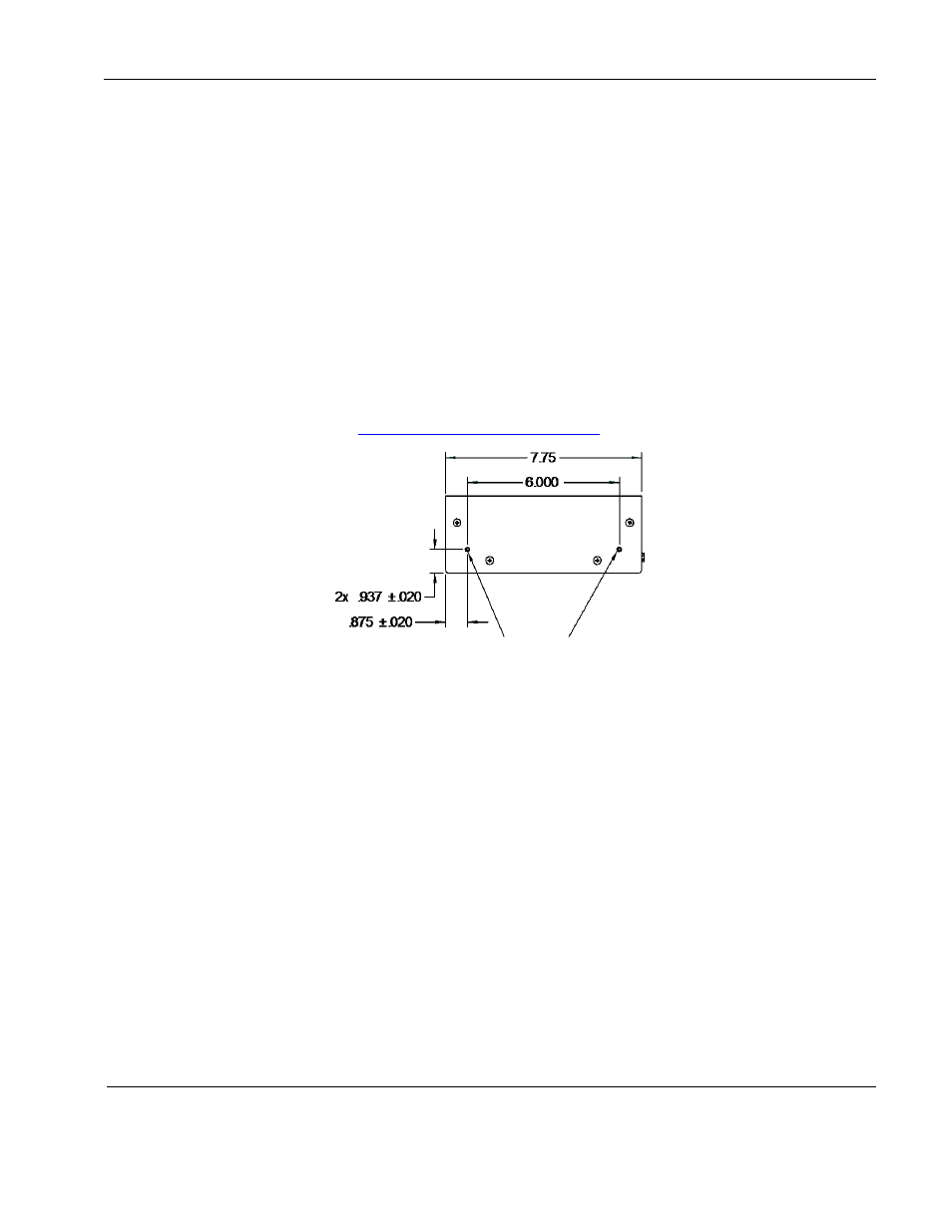
The maximum mounting-screw penetration into the housing does not exceed .25
inches. Two mounting holes are available on each side for 6-32 screws, as shown
below, and on the
Figure 5 RosenView MX mounting requirements
3.
Connect the power and the available inputs, and then press Reset/Power on the front
panel.
Figure 6 RosenView MX rear panel connections
Power input
and Composite
video output
Data input
Monitor VGA