Mounting the sounder, Fig. 1 fig. 2, Fig. 3: internal sounder - pcb diagram – RISCO Group WL Internal Rectangular Sounder User Manual
Page 5
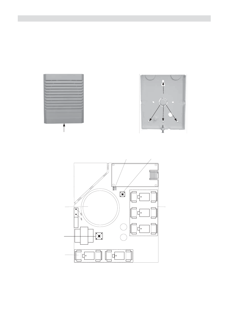
Wireless Sounder Instructions
5
Mounting the Sounder
1. Open the front cover by removing the cover locking screw located at the bottom of the
unit.
2. Hold the back plate against the wall and mark the locations of the mounting holes.
Drill
the desired mounting holes and insert the screw anchors.
3. Mount the back unit to the wall using the supplied screws.
4. Insert the supplied batteries paying attention to the polarity.
5. Perform communication set up with the control panel.
6. Once communication setup is complete, close the cover and locking screw.
Remove cover
locking screw
Fixing Points to
Wall
Fig. 1
Fig. 2
Speaker Batteries
(6V, Serial
Connection)
Speaker
Reset
Switch
S
P
E
A
K
E
R
T
A
M
P
E
R
Two Indication
LEDs
Tamper
Radio Batteries
(3V, Parallel
Connection)
Fig. 3: Internal Sounder - PCB Diagram