RISCO Group WL Dual Channel Transmitter RWT72X User Manual
Wireless dual channel transmitter, Rwt72x, Rok one t 1998
GENERAL DESCRIPTION
The RWT72X is dual function supervised transmitter that can
be connected to two separate external contacts OR to one
external contact and one shutter contact. It operates with
RISCO Group’s receivers and is powered by a 3-volt lithium
battery.
TRANSMITTER MAIN FEATURES:
•
Operates up to 1333ft (400m) range (outdoors)
•
RF high/low power
•
Uses one of more than 16 million pseudo-randomly
selected preset coded addresses for setup (no DIP switches)
•
Microprocessor design
•
Extended battery life
•
Fully supervised
•
Selective function (universal or shutter protection)
•
Selective pulse counter (for shutter control function)
•
Selective response time and input (NO/NC) for universal
control function
•
Back and cover tamper protection
TERMINAL BLOCK WIRING
Two channels can be connected to the terminal block of the
transmitter (See figure 1)
E N G L I S H
INSTALLING THE TRANSMITTER
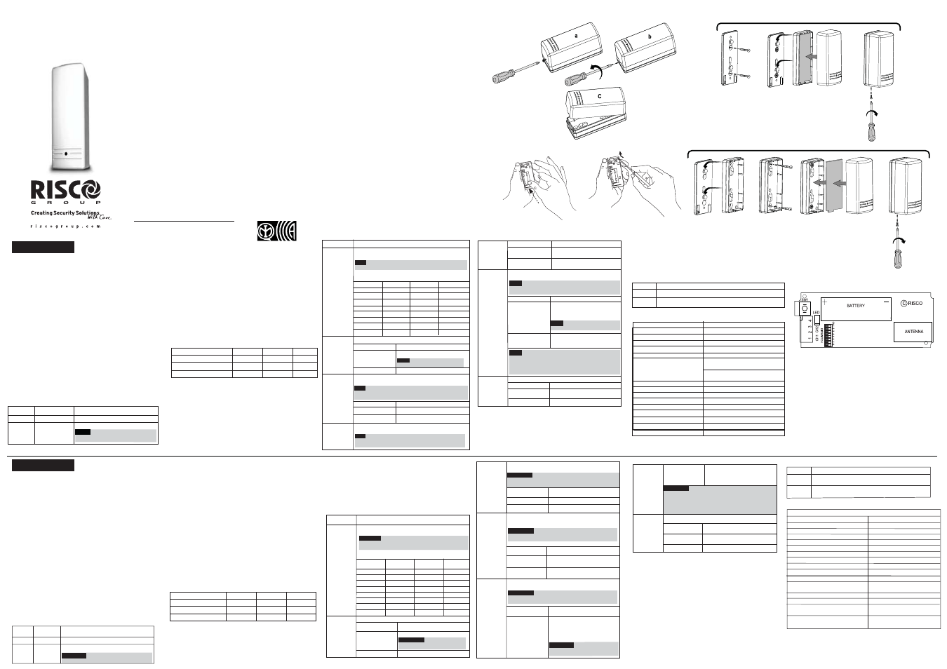
Step 1: Front Cover Removal
Remove the front cover as described in Figure 2.
Step 2: Transmitter/Receiver Communication Set Up
The transmitter must identify itself to the system’s receiver by
writing its coded messages into the receiver’s address
memory. The receiver must identify each channel separately.
This is accomplished byperforming the following steps:
a. Set the receiver to the Write Mode (Follow the receiver’s
instructions).
b. Remove the battery from the insulation material and
reinsert it into the transmitter, paying attention to the
polarity. (See Figure 3).
c. Send a separate Write message to each channel. Use
Dipswitches 4 and 5, as described in the table below, to
choose a channel. All other dipswitches must be in OFF
position. To program the ID of channel 1 set the dipswitches
to the OFF position and send a Write message by pressing
both tamper buttons for at least 3 seconds.
d. To program the ID of channel 2 set dipswitches 4 and 5
according to the required application and send a Write
message by pressing both tamper buttons for at least 3
seconds.
e. Set the receiver to the Normal mode.
f. Verify that the receiver has identified each of the channels
by generating an alarm signal (by momentarily opening
and closing the input terminal of each channel).
Step 3: Dipswitch Settings
After setting the transmitter/receiver communication use the
dipswitches to configure the transmitter operation as
Dipswitch No.
Description
Used for setting the number of pulses for a shutter detector
(channel 2 only).
Note:
If Dipswitch 4 is defined as OFF then dipswitches 1-3
will not be activated.
Set dipswitches 1-3 for the required number of pulses as
shown in the following table:
1 - 3
Dipswitch 1
OFF
ON
Dipswitch 2
Dipswitch 3
No. of Pulses
OFF
ON
OFF
ON
OFF
ON
OFF
OFF
OFF
OFF
OFF
OFF
OFF
OFF
ON
ON
ON
ON
ON
ON
ON
ON
2
4
6
8
10
12
14
16
Dipswitch Position
OFF*
ON
Channel 2 operation mode
Dipswitch Position
ON
4
Used to determine channel 2 functionality.
Shutter Control
Note:
Use dipswitches1-3 to
determine the number of pulses.
Universal Transmitter
Used to determine an external sensor mode for a universal
transmitter.(Channel 1)
Note:
This definition also applies to channel 2 when the
channel is defined as Universal Transmitter (Dipswitch 4:
OFF)
Slow: 500 ms (For operation
with magnetic contacts, etc.)
Normally Closed (NC)
Normally Open (NO)
5
Dipswitch Position
Response Time
Fast: 10 ms (For operation with a
shock sensor)
OFF*
ON
OFF*
* Default
Used to determine the HOLD status of a universal
transmitter. (Channel 1)
Note:
This definition also applies to channel 2 when the
channel is defined as Universal Transmitter (Dipswitch 4:
OFF)
7
Dipswitch Position
Hold Status
ON
Hold is On: There will be 2.5 minutes
dead time between the alarm
detection transmissions. (Restore
messages will be sent immiately).
Note:
Only one alarm message is
transmitted in any 2.5 minute
Hold is Off: No dead time between
alarm detection transmissions (the
unit transmits after each detection).
Note:
In both HOLD status thebfollowing occurs:
1. Disconnecting the detector’s input terminal will send
an alarm after 500 ms.
2. Reopening and closing the detector inputs will
generate an extra alarm and restore messages.
8
OFF*
Used to determine the transmission power:
RF Power Transmission
RF high power
RF low power (when then
transmitter is closed to the
Dipswitch Position
ON
OFF*
Condition
Description
The LED lights momentarily after each detection transmission.
Blink
Indicates LOW battery. The LED blinks after each detection
transmission.
RISCO Group Limited Warranty
RISCO Group and its subsidiaries and affiliates ("Seller") warrants its products to be free from
defects in materials and workmanship under normal use for 24 months from the date of
production. Because Seller does not install or connect the product and because the product
may be used in conjunction with products not manufactured by the Seller, Seller cannot
guarantee the performance of the security system which uses this product. Seller's obligation
and liability under this warranty is expressly limited to repairing and replacing, at Seller's
option, within a reasonable time after the date of delivery, any product not meeting the
specifications. Seller makes no other warranty, expressed or implied, and makes no warranty
of merchantability or of fitness for any particular purpose.
In no case shall seller be liable for any consequential or incidental damages for breach of this
or any other warranty, expressed or implied, or upon any other basis of liability whatsoever.
Seller's obligation under this warranty shall not include any transportation charges or costs of
installation or any liability for direct, indirect, or consequential damages or delay.
Seller does not represent that its product may not be compromised or circumvented; that the
product will prevent any personal injury or property loss by burglary, robbery, fire or
otherwise; or that the product will in all cases provide adequate warning or protection. Buyer
understands that a properly installed and maintained alarm may only reduce the risk of
burglary, robbery or fire without warning, but is not insurance or a guaranty that such event
will not occur or that there will be no personal injury or property loss as a result thereof.
Consequently seller shall have no liability for any personal injury, property damage or loss
based on a claim that the product fails to give warning. However, if seller is held liable,
whether directly or indirectly, for any loss or damage arising under this limited warranty or
otherwise, regardless of cause or origin, seller's maximum liability shall not exceed the
purchase price of the product, which shall be complete and exclusive remedy against seller.
No employee or representative of Seller is authorized to change this warranty in any way or
grant any other warranty.
NOTE: This product should be tested at least once a week.
RTTE Compliance Statement
Hereby, RISCO Group declares that this product is in compliance with the essential
requirements and other relevant provisions of Directive 1999/5/EC.
The Declaration of Conformity may be consulted at: www.riscogroup.com
RISCO Group 12/2014 5IN1296 E
Wireless Dual
Channel Transmitter
RWT72X
6
Used to determine the response time for a universal
transmitter. (Channel 1)
Note:
This definition also applies to channel 2 when the
channel is defined as Universal Transmitter (Dipswitch 4:
OFF)
Step 4: Selection of the Installation Location
a. Select a location best suited for communication quality
and near the intended wired detector (for switched
sensor).
Place the unit at the highest possible position.
b. Temporarily attach the unit to this point using two
sided adhesive tape.
Channel
Terminal Block
Channel Functionality
Channel 1 1 + 2 Universal transmitter
Channel 2 3 + 4 Universal transmitter OR Shutter
N Note:
The functionality of channel
2 is determined by dipswitch 4.
Channel 1: Universal Mode*
Channel 2: Universal Mode
Channel 2: Shutter Mode
Channel
Dipswitch 4
Dipswitch 5
Restore
OFF
OFF
ON
OFF
ON
ON
YES
YES
N0
* Default
UK
Tel: +44-(0)-161-655-5500
E-mail: [email protected]
ITALY
Tel: +39-02-66590054
E-mail: [email protected]
SPAIN
Tel: +34-91-490-2133
E-mail: [email protected]
FRANCE
Tel: +33-164-73-28-50
E-mail: [email protected]
BELGIUM (Benelux)
Tel: +32-2522-7622
E-mail: [email protected]
U.S.A
Tel: +1-631-719-4400
E-mail: [email protected]
BRAZIL
Tel: +55-11-3661-8767
E-mail: [email protected]
CHINA (Shanghai)
Tel: +86-21-52-39-0066
E-mail: [email protected]
CHINA (Shenzhen)
Tel: +86-755-82789285
E-mail: [email protected]
POLAND
Tel: +48-22-500-28-40
E-mail: [email protected]
ISRAEL
Tel: +972-3-963-7777
E-mail: [email protected]
EN50131-1, EN50131-5-3,Grade2(G2), Environmental Class II (EC2)
Specifications are subject to change without prior notice.
Should any questions arise please contact your supplier.
c. Generate an Alarm signal (by momentarily opening or
closing the input terminals) and verify that the receiver
has received the signal. If the alarm signal is not
detected, reposition the transmitter and try again.
Step 5: Final Mounting
Separate the back part of the transmitter (fig. 4), and mount
all the parts in place (fig. 5). If relevant, connect the sensor to
the input terminals.
LED INDICATION
SPECIFICATIONS
Electrical
Battery Type
CR123 3V Lithium Battery
Current Consumption
2•A standby
Low Voltage Threshold
2.5V
Frequency
868.65 MHz / 433.92 MHz
Dead Time (HOLD ON)
2.5 minutes
Supervision Transmission Every 15 minutes (for
868.65MHz models)
Every 65 minutes (for
433.92MHz models)
Modulation Type
ASK
Battery Life
5 years (Upon usage)
Current Consumption 13 mA Transmit; 30 A standby
Physical
Size
81x35x32 mm (3.2x1.37x1.27 in.)
Environmental
RF immunity
According to EN50130-4
Operating temperature -10°C to 55°C (14°F to 131°F)
Storage temperature
-20°C to 60°C ( -4°F to 140°F)
μ
DESCRIPTION GÉNÉRALE
Le RWT72X est un transmetteur supervisés à double
fonction pouvant être reliés à deux contacts externes
distincts OU à un contact externe et à une contact
obturateur.
Il fonctionne avec les récepteurs Groupe de RISCO et
alimenté par une pile lithium 3Volts.
Principales caractéristiques du transmetteur
•
Portée de fonctionnement jusqu'à 400 m (1333 ft.) (en
extérieur),
•
Puissance RF élevée/ faible,
•
Pour l'installation, utilisation de l'une des plus de 16
millions d'adresses codées, préréglées et sélectionnées de
manière pseudo-aléatoire,
•
Conception microprocesseur,
•
Extension de la durée de vie de la pile,
•
Entièrement supervisé,
•
Fonction sélective (protection universelle ou obturateur),
•
Compteur de pulses sélectif (pour la fonction de contrôle
de l'obturateur),
•
Temps de réaction sélectif et entrée (NO/NF) pour
fonction de contrôle universelle,
•
Protection anti-sabotage (Autoprotection) arrière et
couvercle.
CÂBLAGE DES BORNES DE CONNEXION (TERMINAUX) Deux
canaux peuvent être reliés aux bornes de connexion du
F R A N Ç A I S
INSTALLATION DU TRANSMETTEUR
Etape 1: Retrait du couvercle
Retirez le couvercle frontal comme l'indique le schéma en
fig. 1.
Etape 2: Etablissement de la communication Transmetteur/
Récepteur
Le transmetteur doit s'identifier auprès du récepteur du
système en inscrivant ses messages codés dans le registre
d'adresses du récepteur. Ce dernier doit identifier chaque
canal séparément. Cette opération s'accomplit en exécutant
les étapes suivantes :
a. Réglez le récepteur en mode écriture (suivez pour cela
les instructions correspondantes).
b. Retirez la pile de sa protection isolante et réinsérez-
la dans le transmetteur en respectant la polarité
indiquée (cf. fig. 3).
c. Envoyez un message écrit à chaque canal séparément. A
l'aide des commutateurs DIP 4 et 5, sélectionnez un canal
selon les instructions du tableau ci-dessous. Tous les
autres commutateurs DIP doivent être en position d'arrêt
(OFF). Pour programmer l'identification ID du canal 1,
réglez les commutateurs DIP en position OFF et envoyez
un message écrit en appuyant sur les deux boutons
d'autoprotection pendant au moins 3 secondes.
d. Pour programmer l'identification ID du canal 2, réglez les
commutateurs DIP 4 et 5 selon l'application requise et
envoyez un message écrit en appuyant sur les deux
boutons d'autoprotection pendant au moins 3 secondes
Etape 4 : Choix ce l'emplacement de l'installation
a. Choisissez l'emplacement le mieux adapté pour assurer
la qualité de la communication, tout en restant près
du détecteur filaire voulu (pour capteur à liaison
commutée).
b. Fixez provisoirement l'appareil en ce point à l'aide
d'un ruban adhésif double face.
c. Générez un signal d'alarme (en ouvrant ou en fermant
momentanément les terminaux d'entrée) et vérifiez que
le récepteur a bien reçu le signal. Si le signal
d'alarme n'est pas détecté, replacez le transmetteur et
essayez à nouveau.
Etape 5 : Montage final
Séparez la partie arrière du transmetteur (fig. 3) et placez
correctement toutes ses pièces (fig. 4). Si besoin est, reliez
le capteur aux terminaux (ou bornes de connexion)
d'entrée.
L'option d'Attente est inactive : pas
de temps mort entre les
transmissions de détection d'alarme
(l'appareil émet après chaque
détection).
Remarque :
dans les deux cas :
1. La déconnexion du terminal d'entrée du détecteur lancera
une alarme après 500 ms.
2. La réouverture et la fermeture des entrées du détecteur
génèreront une alarme supplémentaire ainsi que des
messages de restauration.
Arrêt (OFF)*
Lent : 500 ms (en fonctionnement
avec des contacts magnétiques, etc.)
6
Sert à déterminer le temps de réaction pour
transmetteur universel. (Canal 1)
Remarque :
cette définition s'applique également au
canal 2 quand le canal est défini comme transmetteur
universel (commutateur DIP 4: à l'arrêt (OFF).
Rapide : 10 ms (en fonctionnement
avec un capteur de chocs).
Sert à déterminer la position d'ATTENTE d'un
transmetteur universel. (Canal 1)
Remarque :
cette définition s'applique également au
canal 2 quand le canal est défini comme transmetteur
universel (commutateur DIP 4: à l'arrêt (OFF).
7
Positon d'ATTENTE
L'option d'Attente est active : un
temps mort de 2,5 minutes sera
respecté entre les transmissions de
détection d'alarme. (Des messages
de restauration seront envoyés
immédiatement).
Remarque
:
Une seule alarme est
transmise sur une période de 2,5
minutes.
Temps de réaction
Position du
commutateur DIP
Marche (ON)
Arrêt (OFF)*
Position du
commutateur DIP
Marche (ON)
INDICATEURS LED
Canal 1 1 + 2 Transmetteur Universel
Canal 2 3 + 4 Transmetteur Universel OU à obturateur
Remarque
:
la fonctionnalité du canal 2 est
définie par le commutateur DIP 4.
Canal
Bornes de
connexion
Fonctionnalité du canal
Canal 1 : mode universel*
Canal 2 : mode universel
Canal 3 : mode obturateur
* Option sélectionnée par défaut
Commutateu
r DIP 4
Commutate
ur DIP 5
Restauration
Arrêt (OFF)
Arrêt (OFF)
Marche (ON)
Arrêt (OFF)
Marche (ON)
Marche (ON)
OUI
OUI
NON
Temps de réaction
Normalement fermé (NF)
Normalement ouvert (NO)
5
Commutateur
DIP n°
Description
commutateur
DIP 1
Arrêt (OFF)
Marche (ON)
Arrêt (OFF)
Marche (ON)
Arrêt (OFF)
Marche (ON)
Arrêt (OFF)
Marche (ON)
Servent à régler le nombre de pulses pour un détecteur à
obturateur. (canal 2 seulement).
Remarque :
si le commutateur DIP 4 est réglé en position
d'arrêt (OFF), les commutateurs DIP 1 – 3 ne s'activent
pas.
Réglez les commutateurs DIP 1 -3 sur le nombre de
pulses requis comme l'indique le tableau suivant :
2
4
6
8
10
12
14
16
1 - 3
Position du
commutateur DIP
Arrêt (OFF)*
Marche (ON)
Mode de fonctionnement du
canal 2
4
Sert à déterminer la fonctionnalité du canal 2.
Contrôle de l'obturateur
Remarque
:
à l'aide des
commutateurs DIP 1 – 3,
déterminez le nombre de pulses.
Transmetteur universel
commutateur
DIP 2
Arrêt (OFF)
Arrêt (OFF)
Marche (ON)
Marche (ON)
Arrêt (OFF)
Arrêt (OFF)
Marche (ON)
Marche (ON)
commutateur
DIP 3
Arrêt (OFF)
Arrêt (OFF)
Arrêt (OFF)
Arrêt (OFF)
Marche (ON)
Marche (ON)
Marche (ON)
Marche (ON)
Nombre de
pulses
Position du
commutateur DIP
Marche (ON)
Arrêt (OFF)*
* Option sélectionnée par défaut
8
Sert à déterminer la puissance de transmission.
Transmission de puissance RF
Puissance RF élevée
Faible puissance RF (lorsque le
transmetteur est fermé au récepteur).
Position du
commutateur DIP
Marche (ON)
Arrêt (OFF)*
Voyant
Description
Allumé
L'indicateur LED s'allume momentanément après
chaque transmission de détection.
Clignotant
Indique que la pile est faible. L'indicateur LED clignote
après chaque transmission de détection.
f. Vérifiez que chaque canal a bien été identifié par le
récepteur : pour ce faire, générez un signal d'alarme (en
ouvrant et fermant momentanément la borne d'entrée
de chaque canal).
Etape 3: Réglage des commutateurs DIP
Après avoir établi la communication transmetteur/
récepteur, servez-vous des commutateurs DIP pour
configurer le fonctionnement du transmetteur comme
indiqué dans le tableau ci-dessous :
Sert à déterminer le mode d'un capteur externe pour
transmetteur universel. (Canal 1)
Remarque :
cette définition s'applique également au
canal 2 quand le canal est défini comme transmetteur
universel (commutateur DIP 4: à l'arrêt (OFF).
Spécifications techniques
Electriques
Type de batterie (piles)
CR123, Pile lithium 3V
Consommation électrique 2•A en veille
Seuil de tension basse 2.5V
Fréquence
868,65 MHz / 433,92 MHz
Temps mort (ATTENTE)
2,5 minutes
Transmission de la supervision toutes les 15 minutes
Type de modulation
ASK
Durée de vie de la pile
5 ans (Sur l'utilisation)
Consommation électrique: 30μA en veille;
13mA dans la transmission
Physiques
Dimensions
81 X 35 X 32 mm
(3,2 x 1,37 x 1,27 in.)
Environnementales
Immunité RF
Selon EN50130-4
Température de fonctionnement de -10°C à 55°C
(14°F à 131°F)
Température de stockage de -20°C à 60°C
(-4°F à 140°F)
Ces spécifications sont susceptibles d'être modifiées sans avis
préalable.
Pour tout renseignement, veuillez contacter votre
Fig. 1
Fig. 2
Fig. 3
Fig. 4
Fig. 5
Option A
Option B
©
ROK
ONE
T
1998