Section 4: troubleshooting – Precision Medical HeliO2 Blenders User Manual
Page 28
Heliox / Oxygen Blender Service Manual
Page 26
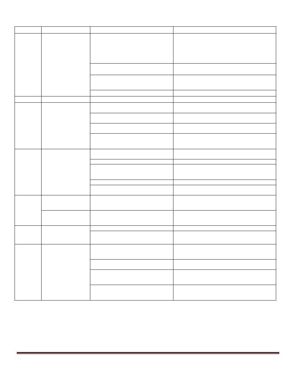
SECTION 4: TROUBLESHOOTING
Test #’s Problem
Probable Cause
Remedy
1
Pressure drop greater
than 2 psi in two
minutes
Leakage from manifold caused by cut or
missing o-ring or due to particulates.
Check ALL manifold connections (inlets, outlets,
plugs, proportioning valve, alarm poppet, etc.) with
Oxygen leak detector to find source of leakage; if
leak is found, remove appropriate parts and clean
seal area and o-rings and/or replace appropriate
o-ring.
Ball not sealing in the alarm bypass.
Replace spring and ball in alarm bypass; ensure
seal surface is clean.
Auxiliary bleed is open.
Close auxiliary bleed by turning and pulling
knurled collar away from cover until bleed is
closed.
Leakage from one of the outlets.
Replace outlet.
2 and 3
Back flow leak
Faulty inlet.
Replace duckbill valve or entire inlet assembly.
4 thru 8
Measured
F
IO
2
values
do not meet target
values
Outlet flow is less than 3 lpm.
Adjust flowmeter to 3 lpm (Note: flow must be
adjusted after each change in
F
IO
2
setting).
Proportioning valve endpoints are not
set correctly.
Set proportioning valve endpoints (See setup
procedure in Section E).
Diaphragm blocks not balancing
properly.
Replace Diaphragm Blocks.
Internal leakage in proportion valve.
Remove proportioning valve; clean seal areas
and/ or replace the two rear o-rings. If necessary,
replace proportioning valve assembly.
9 thru 11
Measured
F
IO
2
values
do not meet target
values
Bleed not open.
Open bleed by turning and pushing the knurled
collar until it contacts the cover.
Blockage in bleed holes.
Replace auxiliary outlet.
Internal leak in proportioning valve.
Remove proportioning valve; clean seal areas
and/ or replace the two rear o-rings. If necessary,
replace proportioning valve assembly.
Flow not set to 1 lpm.
Adjust flow to 1 lpm.
Diaphragm blocks not balancing
properly.
Replace diaphragm block.
12
And
14
Alarm not audible and
gas is not exiting the
alarm vent
Pressure differential not sufficient to
trigger alarm.
Ensure supply pressures are set properly to
achieve differential (Low Flow: 18 to 22; High
Flow: 13 to 25).
Alarm not audible and
gas is exiting the
alarm vent
Faulty alarm.
Replace alarm. (See Figure C & K)
13
And
15
Alarm does not turn
off after balancing
supply pressures
Faulty alarm assembly.
Replace alarm assembly. (See Figure C & K)
Ball not sealing in the alarm bypass.
Replace spring and ball in alarm bypass; ensure
seal surface is clean.
16
Thru
19
Measured flow values
do not meet minimum
target values
Gas inlets are restricted.
Check appropriate gas inlet(s) for restriction in gas
pathway; replace duckbill or entire inlet as
necessary.
High flow model only: low flow inlets
installed in place of high-flow inlets.
Confirm that high-flow inlets are installed; replace
as necessary.
Alarm bypass is threaded too far into
manifold block (only applicable to tests
17 and 18).
Replace ball and spring (see Figure I for proper
assembly method).
High flow models only: wrong ball in
alarm bypass block (only applicable to
tests 17 and 18).
Confirm that correct ball is installed in alarm
bypass; replace as necessary.