Connections – Precision Digital PD6770 User Manual
Page 9
PD6770 Loop-Powered Process Meter
Instruction Manual
9
Connections
WARNINGS
Static electricity can damage sensitive components.
Observe safe handling precautions for static-sensitive components.
Use proper grounding procedures/codes.
If the meter is installed in a high voltage environment and a fault or
installation error occurs, high voltage may be present on any lead or
terminal.
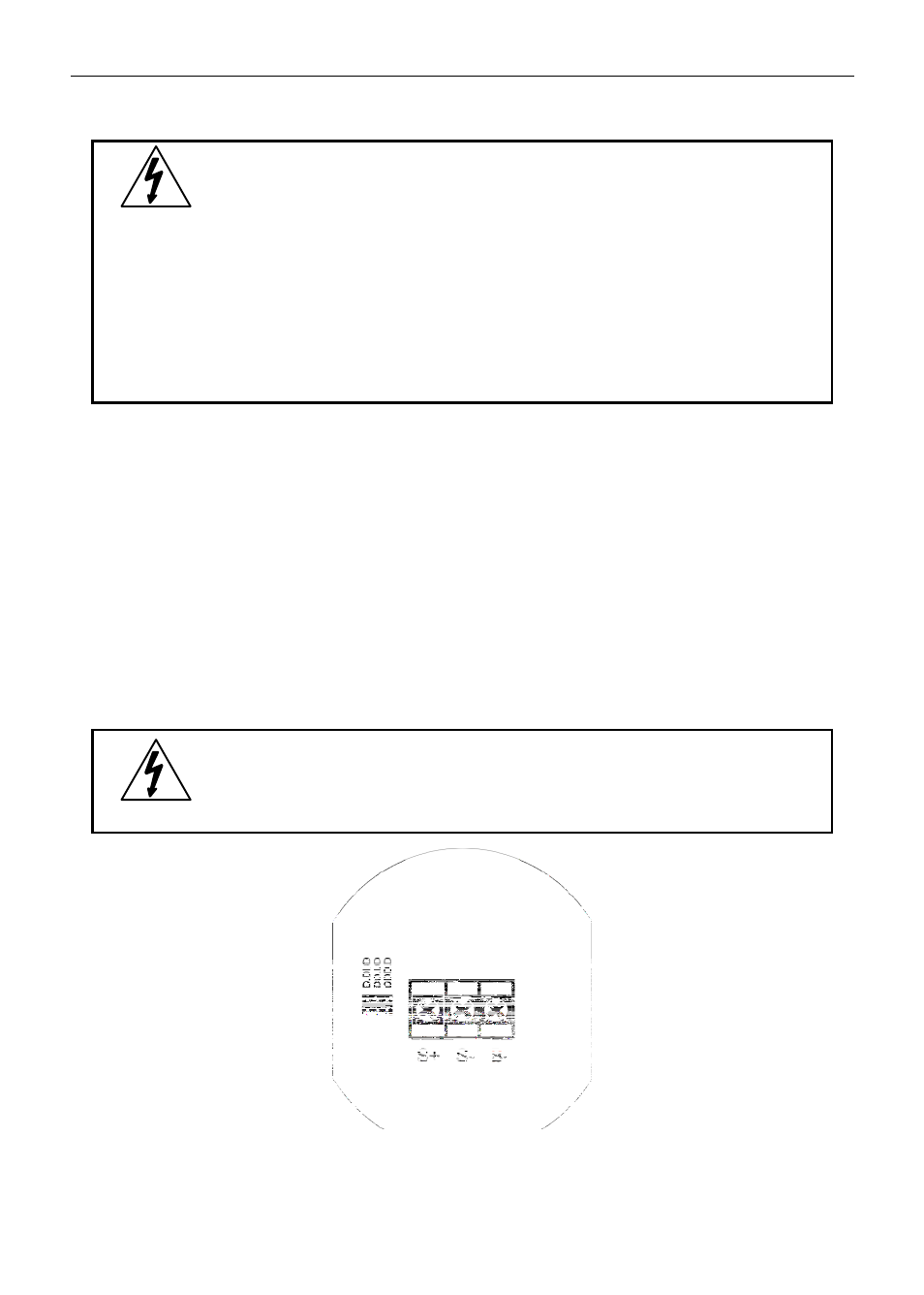
To access the connectors, remove the enclosure cover and unscrew the two captive
screws that fasten the display module. Remove the display module. Signal
connections are made to a three-terminal connector on the rear of the display
module.
S+
4-20 mA signal input positive terminal connection
S-
4-20 mA signal return/negative terminal connection
B-
4-20 mA signal return/negative terminal when using the installed loop
powered backlight option.
Refer to Figure 1 for terminal positions.
WARNING
Observe all safety regulations. Electrical wiring should be
performed in accordance with all agency requirements and
applicable national, state, and local codes to prevent damage to
the meter and ensure personnel safety.
Figure 1. PD6770 Connectors